| Canadian Pacific Odds and Ends - Part 6 Articles |
The Last Passenger Train - Maine Magazine 1977. The "Last Call" page has appeared weekly on OKthePK's web site over the past couple of years. Each week a different article told the story about various railway items of interest. While some of the articles were saved they were no longer available online. Several of those about the Canadian Pacific Railway have been compiled here on this page. There is insufficient room to display more than a few articles per page. As a result, "Canadian Pacific Odds and Ends - Part 6", continues this month with more possible parts to follow as time progresses. Every month they will be archived to the CPR Set-off Siding web site for future online retrieval. Look under the articles section on the CPR Set-off Siding web site to find these archived pages. 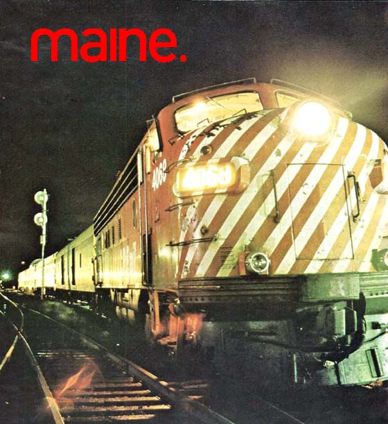 Story by Phil Willem's Photos by Lavey PincusNothing short of the total destruction of all highways would make the Atlantic Limited a paying proposition. The train rolls in at half past midnight. It is quiet in Brownville Junction and you can hear the plaintive song of the big diesel's air horn in the distance well before the engine's brakes sigh and the iron wheels squeak as the train reluctantly comes to a stop. A new crew will take over here, union rules. Only rarely does a new passenger slip silently on board to take an inconspicuous place in a dark corner of the lounge or one of the 19 sleeping berths for the eight hours that remain of the journey to Montreal. By a quirk of political geography the state of Maine juts up between Canada's Atlantic Provinces and Quebec. When the Canadian Pacific Railway Company looked eastward in 1889 after linking central Canada with the West Coast it seemed only logical to lay track as the crow flies, and that meant cutting a swath through the spruce and pine forests of northern Maine. From Vanceboro to the Quebec border near Jackman lie 180 miles of track traversed nightly by the Atlantic Limited, linking St. John, New Brunswick. and Montreal. It is the last passenger train in Maine.
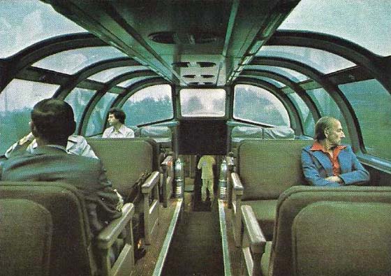
Once we boarded, it didn't take long to get settled. Most of the train was dark, its passengers silent. In the observation car rain splattered on the glass dome but didn't disturb sleepers who were saving from $12 to $30 by spending the night sprawled over two or three seats instead of taking a berth or room. Photographer Howard Pincus and I were lucky, Canadian Pacific public relations man Steve Morris supplied us with one of the train's five double rooms. Although sleeping compartments are small, the beds are comfortable. Walls are pale pink, fixtures stainless steel, ugly but functional. I was awake long enough to see the train pause at Greenville but somewhere between Brassua Lake and Long Pond the sound and motion put me to sleep. Five hours later I rose to the sight of Quebec's flat farm country gliding by, surprised that Canadian Customs hadn't roused us when we crossed the border. Either they didn't know we were on board or they didn't care. About 50 miles cast of Montreal, while I sipped coffee and tarried over my ham and eggs, we started to pick up commuters, businessmen with La Presse or the Gazette tucked under one arm, families going into town for a day of shopping. Although shopping is a good reason for going to Montreal it is by no means the only one. There is also music, theater, excellent dining, and skiing in the nearby Laurentians to make the city worth a visit.
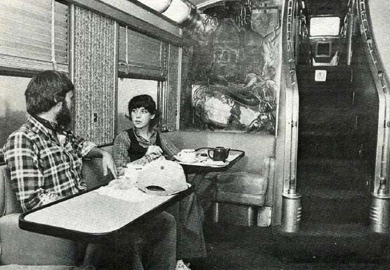
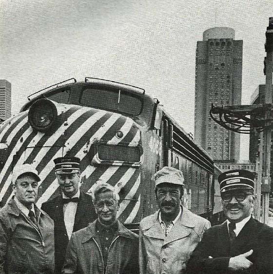
Canadian businessmen who use the train often cite that timing as a good reason. They'd have to spend the night in a hotel anyway so they leave St. John at 8:50 in the evening, sleep on the train, and arrive in downtown Montreal at 8:50 next morning rested and ready to do business. Could fear of flying motivate train passengers? No, at least not overtly. Not one of the passengers I talked to admitted being afraid to fly, although several expressed a dislike for planes, too fast, too plastic. What most of them apparently appreciate about the train is that it comes close to their vague vision of the romance of travel in a way that the antiseptic pre-packaged materials-handling approach of air travel never will. On the train they are human beings, they can sit down to a real dinner, US$4.95 for poached fish in Hollandaise sauce, not an aluminum tray with yesterday's fried chicken and overcooked peas. To avoid confusion Canadian Pacific requires diners to place written orders, perhaps because of the complications of bilingualism and a crew that alternately comes from Quebec and New Brunswick. You scratch out your gustatory wishes while the train sways pleasantly from side to side. It makes you feel like an uncoordinated 6-year-old struggling to keep your first letters within the boundaries of widely spaced blue lines on pulpy newsprint. Very frustrating. Editor's Note: Written menu orders were also used on The Canadian and the Dominion trains. Not that the ride is rough. Photographer Pincus, a train freak, points out that CP has maintained the tracks. Bad track, it seems, begets a bad ride. I had never known that. I had assumed that trains were trains and God had given them the right to clatter and sway while they carried you to your destination. But as I later found out, Howard was right. CP has indeed spent time and money to keep the track and the rail bed in good repair. They've just completed a five-year, US$10 million track rehabilitation project, over 304 miles of the Atlantic's route. To facilitate the heavier and longer freight trains that CP anticipates from increased container shipping through the port of St. John, 120 workers replaced 250,000 railroad ties, and beefed up the rail bed with 1.5 million tons of heavy grade ballast. A US$10 million investment in railroads is an act of faith if not foolishness. CP must believe that its freight operation warrants that kind of capital outlay, for its passenger service clearly does not. "I know of no rail passenger system in the world today that pays its own way," says A.R. (Gus) Campbell, CP's General Manager of Passenger Services. Campbell's view of the situation is realistic to the point of fatalism. "We've proven to ourselves that people don't want to travel by train," he says. And he doesn't think that higher gasoline prices are going to make any difference. "Here in Canada we're up over a dollar a gallon (imperial) now and we don't see our business picking up. Even at $5 a gallon I think people would drive their cars." Aren't there any conditions under which he could see passenger service making money? "I could imagine it," he says, "only imagine it, if all roads were destroyed." 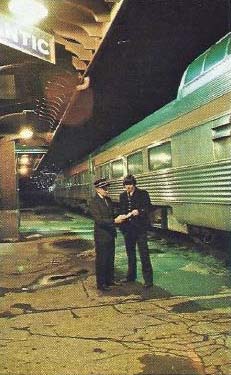 Nor does Campbell, think promotion and advertising might bring enough riders to make the train pay. He points out that, "Between 1955 and 1969 CP allocated US$15 million to advertising and our losses increased every year." More passengers don't necessarily mean profits anyway. "A Canadian National Railroad Vice President has said that the more passengers you carry the more money you lose," Campbell says. "and I agree with him." Organizationally, CP Rail's passenger service is now in limbo awaiting the imminent consolidation of all passenger service under the management of VIA Rail Canada, a government corporation that is the Canadian equivalent of Amtrak. After consolidation CP Rail will provide passenger service under contract to VIA Rail and so will get out from under the 20 percent of its operating loss that it bears. (A government subsidy now picks up only 80 percent of the deficit.) CP hopes that the contract arrangement with VIA Rail will enable them to run passenger trains without the burden of keeping obsolete equipment in safe operating condition. Campbell would like to be able to buy new equipment for CP's passenger trains. Both cars and engines on the Atlantic Limited are at least 20-years-old. Although the stainless steel coaches have been superbly maintained, their age shows. The interiors look, well, 50's-ish and I could understand why Campbell would say one of the reasons he'd like to get new cars would be to bring decor "into the 20th century." The Atlantic once carried a full dining car, today meals are served in what is known as a club car, which is used to serve drinks and snacks on CP's transcontinental run. Until 1969 every table boasted a vase with a cut rose, and silverware, not stainless steel, graced the place settings of CP diners. It seems to genuinely pain Campbell that it has become economically impossible to maintain that sort of elegance. "It's a matter of pride," says Campbell, "CP's passenger service set a standard as high as any in the world." To me, accustomed to Amtrak's perfunctory personal attention and packaged snack-bar food, CP's standards still seem something to be proud of, but all who knew it in the past insist that service isn't what it used to be. "It's sad to see something go that has been so much a part of the country," Campbell sighs. "It's sad, it's a shame, it's a pity," so many people's feeling for passenger trains are tinged with that kind of melancholy regret. Affectionate sympathy for an old friend who couldn't quite cut it in the hurly-burly of a changing world. I think people sense the loss of travel as a communal activity, the shared experience of going from one place to another. Neither automobiles, buses, nor airplanes transform a group of strangers into "fellow travelers" the way trains do. Ocean travel works much the same magic, but has always been too much the privilege of the wealthy for its demise to warrant any tears. So the world cries for its dying passenger trains, all the while strangling them with under priced gasoline and endless miles of subsidized highways. And unions. The men who work on the railroad are among those who mourn the decline of passenger service. "It's a shame more people from Maine don't ride the train," says Walter Sullivan, a spare, silver-haired man, impeccably dressed in his starched and pressed CP conductor's uniform, his old switch keys still hanging from his belt. Sullivan has been with CP since 1942, making him third "oldest" in the Brownville Section. "Age" is measured in years of service and on the railroad age is everything. So Sullivan's seniority qualifies him for the more desirable tasks in the section. Until two years ago he rode the freights, now he's conductor on the Atlantic Limited. He rides from Brownville Junction to Megantic, Quebec, "lays over" in a company bunkhouse for 18 hours, then works the return trip the following night. Many argue that railway unions are one of the prime reasons for passenger service's inability to make ends meet, and you don't have to be a reactionary capitalist to see merit in their argument. CP' archivist Omer Lavallee explains that in the early days of steam, locomotives ran for about 100-125 miles at a stretch. That's how far they could go before they needed major servicing. Railroad administrative units called sub-divisions or sections arose corresponding to that 100-mile length, and when union rules were laid down, covering one sub-division became a day's work. Rightly so, for a man deserved a rest after shoveling coal for the eight hours needed to cover that distance. Although coal has gone, the definition of 100-125 miles as a railroader's day hasn't, so crews on the Atlantic punch tickets or write tip baggage forms while the train covers its 117 miles. That takes three hours and ten minutes, by no stretch of the imagination a full day. Could the good greying men of the railroad, diligent, honest men like Brownville Junction's Walter Sullivan be helping bring passenger service to its knees? It seems so. Gus Campbell claims that while labour's share of total operating cost should be no more than 50 percent, it is in fact closer to 60 percent, and productivity is, if anything, declining. A few U.S. railroads are apparently facing down the unions, hoping to wrestle labour costs back into line. But even a non-union railway would probably find it tough to cash in on passenger service. In fact, using Campbell's figures that show CP Rail collecting only about a third of a trip's total cost, you can quickly calculate that passenger service wouldn't turn a profit even if labour were absolutely free.
On another level, driving a car entails a lot of hidden costs that don't show up in the price system at all. Pollution, noise, crowding, inefficient use of non-renewable energy sources, all impose a non-market cost on society that the individual car owner doesn't pay. Trains are generally presumed to subject society to far fewer of these "external" costs. Even so, it is dubious whether forcing such costs into the market system would boost the railroads' competitive strength enough to drag them up from the depths of red ink. What is certain is that without a dramatic restructuring of the market to let it reflect the many costs we now force it to ignore, passenger trains do not stand even a fighting chance, and the Atlantic Limited will indeed have been the last passenger train in Maine. Maine - December 1977
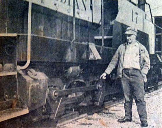
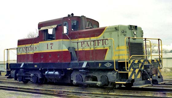
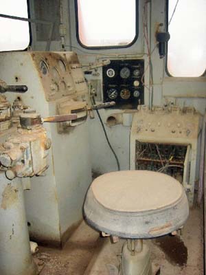 But in the CPR station here, engine number 17 combines the features of both worlds, diesel engine plus side rods. The engine is one of 20 built in 1959 in Kingston on an east European design. But railway officials found they required too much maintenance and they were soon replaced. Except number 17. She is still used as a switch engine in the station yard, even if she needs lots of loving care, which she gets from maintenance man Allan Campbell and engineer Donald Lamont.

The Various Systems in Use Today. What They Aim to Accomplish. How They do it. How the Systems are Cared for.
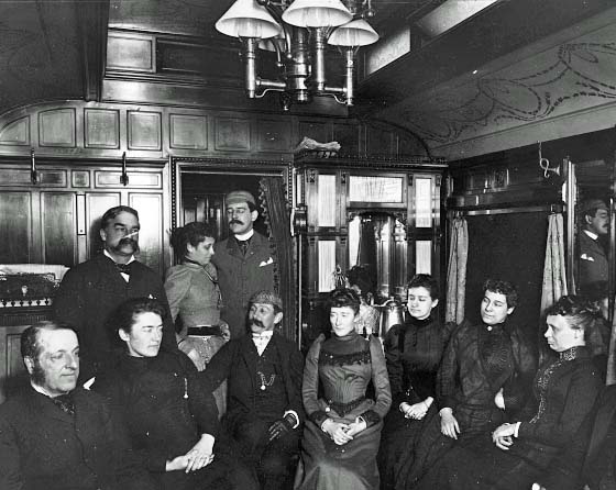
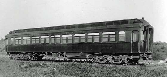
Electric Light: In presenting a paper on the methods employed at the present day for lighting railway passenger cars, Mr. E.S.M. Macnab, engineer of electric car lighting on the C.P.R., to the Canadian Railway Club at a recent meeting said, among other things, that he did not desire to go into technicalities too deeply. The demand for electric lighting had increased for several reasons, among them was safety, the possibility of fire from a wreck was practically nil where electricity was used. Comfort was represented by the possibility of berth lights, and fans could be used in hot weather. The electric light was cool and clean and used up no air, and these lights could be placed where required and could be lighted or turned off as desired. A table showing the equipment as it stood in 1911 and 1914 is here given: Table Showing Electrically Lighted Cars 1911 to 1914
Note - Figures of other roads in U.S.A. not included.
The systems employed may be divided into three main systems, Straight Storage, Head End, and Axle systems. A brief description of each may not be out of place. First, the Straight Storage System. This consists of a set of storage batteries contained in battery boxes under each car, the batteries being connected to the lamps by wires and controlled by a switch. This is certainly the simplest method of lighting, but we find the batteries have to be charged at each terminal, or after every eighteen or twenty-four hours, which necessitates the car being held in the terminal yard from 6 to 10 hours. It is apparent that this system is out of the question for transcontinental service. The chief user of this system is the Pennsylvania Railway, which operates almost sixteen hundred cars on its local trains, also baggage and day coaches on most of its through services, the dining, sleeping, and parlor cars, which have a heavy lamp load, being all lighted with the Axle System. Another disadvantage which this system entails is the heavy capital cost of installing the necessary battery-charging facilities at all terminals. It is interesting to note that at one of the New York yards three hundred and fifty outlets have been installed, each outlet having a separate pair of wires back to a switchboard in the power house. Power is obtained from three 250-k.w. motor-generator sets, giving 110 and 220 volts. The Head End System is a steam-driven generator in the baggage car, as close to the locomotive as possible, from which it draws steam. The equipment consists of a 20 to 25 k.w. turbo-generator, controlled from a switchboard from which three main cables run overhead throughout the train. As the turbine must stop when changing engines or when standing in a terminal before the engine is coupled up, storage batteries have to be used. The Northern Pacific practice is to install 200 ampere-hour batteries on postal car, dynamo car, standard sleepers, and the observation car of each train. The baggage man is instructed so that he can operate the electrical equipment. A disadvantage here exists, however, that when trains are switched off at junctions and others put on, this necessitates the installation of electrical apparatus on a larger proportion of cars than would otherwise be necessary, thus increasing capital and maintenance costs. The steam consumption in the turbine is high, especially in the winter. On the NP axle devices have been used, consisting of a large axle-generator driven by a Morse silent chain, a generator, and a lamp regulator. Thirteen trains have been so fitted. The next system, and one largely adopted, is the Axle System. A generator is driven by a belt from the axle and a set of storage batteries go with the outfit. The design of the axle device involves overcoming five problems. These are (1) Universal polarity, due to the change in direction of rotation of the armature, when the car reverses the direction in which it runs; (2) The maintenance of a constant output in horsepower, irrespective of the speed of the train, after the generator reaches its maximum, which is 22 to 25 mph; (3) The lamp voltage must be held constant at the normal voltage, which is 30 in the United States and generally 24 in Canada, whilst the generator is running at a voltage of 40 in the United States and 30 in Canada; (4) The batteries must receive a sufficient charge to replenish the loss of current consumed at terminal stops, but at the same time must not overcharge them; (5) An automatic arrangement must connect the generator to the batteries when the speed of the train is such that the generator voltage is equal to that of the battery, and disconnect them when the speed falls below that point. To meet the foregoing conditions there are about a dozen patent systems in use in Europe, none of these have ever been adopted in this country, with the exception of the Stone System, which is extensively used in Canada. In the United States there are five principal systems, namely, Gould, Safety, Consolidated, United States, and the E.S.B. In the Stone System the change of polarity is effected by means of a rocking arm which is turned through an angle of about 30 degrees by a friction gear attached to the end of the armature shaft. Constant output is maintained by means of suspending the generator out of center and by means of a tension screw in the suspension, so that it is possible to vary the tension of the belt to give the desired watt output. This method of regulation appears at first sight to be rather crude, but it is surprising how well it acts in actual practice. Lamp Voltage Control is obtained by the use of two batteries, one being charged while the other "floats" across the lamps. The floating battery and lamps are supplied with current from the generator through fixed resistances in multiple, which are connected so that when certain circuits are switched on, a resistance is also switched in multiple with the others, by this means it is possible to obtain close regulation with a varying lamp load. By means of specific gravity tests of the batteries, it is possible to regulate the tension of the belt so that the total output on the trip will take care of the lamp consumption and at the same time keep the batteries fully charged. A battery change-over switch is also used to reverse the charging and regulating battery at each stop. This is operated by a governor attached to the end of the armature shaft, in conjunction with the friction gear and rocking arm, operating a switch, which closes when the generator voltage equals that of the battery. The later design of Stone generator involves the use of an electrically operated automatic switch and pole changer which eliminates the mechanically operated switch gear on the generators now in use. The Safety and Gould equipment have many points in common. The change of polarity is effected in the Safety system by means of rocking the brush holder through an angle of 90 degrees by means of the friction between the brushes and the commutator. In the Gould system a double-throw switch is operated by means of a "dog" attached to the end of the armature shaft engaging a cam when the direction of the rotation is changed. In both systems the voltage of the generator is held constant by a voltage coil connected across the brushes, this coil operates a solenoid which, by a lever, reduces the pressure in a carbon pile in series with the "field". Lamp voltage control is obtained by inserting a carbon pile in the lamp circuit, the pressure of the discs being regulated by means of a solenoid connected across the lamp mains. As the voltage increases, the solenoid operates to reduce the pressure on the pile, thus increasing the resistance in the circuit. In the Gould system a pilot or small carbon pile is introduced to operate the large carbon pile with the object of giving finer adjustment in the system, the main pile is short-circuited when the car is at rest, and allows the battery to feed the lamps direct. In both systems the voltage of the generator is maintained constant. As the battery becomes charged its voltage rises until it equals the generator, when the charge is reduced to about 3 amps. A series coil, in conjunction with the voltage coil of the generator regulator, operates the carbon pile in the field, preventing the output exceeding a predetermined amperage. An automatic switch, which governs the change from generator to battery, is electrically operated, a voltage coil being connected across the brushes, which lifts a switch when the generator voltage reaches the battery. The United States lighting system provides for the change in polarity of the generator, by rocking the brush holders through an angle of 90 degrees. The generator regulation is governed by a carbon pile in series with the field, which is operated by a solenoid. The lamp regulation is also taken care of by a carbon pile in series with the lamp circuit, which is operated by a shunt coil connected across the lamp mains. A feature in this system is the control of the battery charge by the ampere hour meter. The later Consolidated equipment use a similar arrangement. The E.S.B. system presents several features of interest, using the Rosenberg generator on which the main brushes are short-circuited, the armature current being collected from two main brushes at 90 degrees to the auxiliary short-circuited ones, the polarity of this generator always remains the same. The generator voltage is constant, irrespective of speed, by a Wheatstone bridge connected across the field, and as this voltage is set to thirty-six, charging 16 cells in series, it is said to be impossible to overcharge the batteries. Owing to this low charging voltage, the lamp regulator is dispensed with. It is necessary, however, to use 34-volt lamps, which are not a standard. The principal claim of this system is that there are no moving parts on the generator regulator except the automatic switch, and that it is not hard on the battery. The system has been applied to a number of cars on the Santa Fe Railway. If a number of electricians who operate electric-lighting equipment were asked to name the details which cause the most trouble, certainly 90 percent would reply the batteries. The battery is not a source of power, but simply retains electrical energy when charged from the axle generator or yard plant. It is composed of a number of positive and negative lead plates which are insulated from each other by means of hard rubber or wood separators, these plates being immersed in a solution of sulphuric acid, and the whole contained in a lead-lined holder. Each set of plates are burned on to a bridge to which lead lugs are attached for connecting to the next cell. The method of determining the state of charge is usually by means of the hydrometer. The voltage test is also used, a fully charged cell reading 2.2 volts on discharge and gradually dropping to 1.8 volts per cell on full discharge. The capacity depends on the area of these plates, and as a rule in car-lighting service, varies from 250 to 350 ampere hours at the eight-hour rate. To maintain a storage battery in good working condition it should receive 25 percent more charge than discharge, but continuous overcharging causes the plates to buckle and creates an excessive deposit. Either of these causes a short circuit. Overcharge increases the evaporation of the electrolyte, which, if not replaced causes damage. Undercharge also operates adversely, as the action of acid on the plates in a discharged condition forms sulphate of lead, which reduces the capacity of the cell. A charge in a set of batteries gradually leaks out when left standing for a long time, and cars should not be stored where there are no charging facilities existing if it is possible to avoid it. Current may leak to the earth through the lead-lined tanks. At the point of leakage a hole is eventually formed through electrolytic action. This happening in one cell will probably start the rest in that battery box. To prevent this, the outside of the cells and floor of the battery boxes must be as dry as possible and also insulated from the metal work of the cars. The question of organization is the chief factor to be determined if efficient results are to be obtained, in fact it is difficult to convince some management that such is even required. To illustrate the capital expenditure and maintenance costs, take, for example, a road having 400 electric-lighted cars. As each installation will cost, say $1,500, we have a total expenditure of $600,000, of which $800 per car or a total of $320,000 is liable to be permanently destroyed through want of attention. Again let us consider the maintenance cost per car per month. Assuming a total of 400 cars at a cost of $12 per car per month, we have a cost of $4,800 per month, or $57,600 per annum. To show how these costs may be increased or reduced, a few figures may serve to illustrate the effects of closely watching the performance of the equipment. Suppose that by better handling we save one lamp per car per month, we effect a saving of $180 per month, or $2,160 a year. As to the battery, a conservative estimate will place the life of a set at five years. Assuming we have twenty-four batteries per equipment and we increase their life by one year, taking the cost of the batteries as $630, we have: Depreciation at 5 years... $126 per annum Multiply by 400 cars and we have $8,400 a year saved. As to belt life, a saving of one belt per car per annum will approximate $5 for each car in a year, or $2,000 on 400 cars. Summarizing we have: Saving of one lamp per car per month... $2,160 per year The above reasoning may be applied to various details of the equipment which would increase the amounts saved, but the figures in themselves show what may be saved or lost through properly handling or neglecting the equipment, setting aside the discomfort caused to passengers due to light failures. The work which has been accomplished by the Association of Railway Electrical Engineers, in conjunction with the train-lighting committee of the Master Car Builders' Association, and the various manufacturers, has resulted in the working out of various standards and specifications which have assisted in raising the art of electric lighting of passenger cars to its present satisfactory state.   Coil Car One more sample of Canadian Pacific's program of adapting the car to the cargo is the covered steel coil car built to specifications for the special handling of coiled sheet-steel rolls. This flat car with two large fitted covers which are lifted one section at a time by a crane while the weighty coils are loaded into sloped troughs. Crossbars prevent longitudinal movement of the coils during transit. The car has two separate sections with a partition between. Coils up to 84 inches in outside diameter can be carried.  Pressure Unloading Car Combining all-weather protection in transit with contamination-free unloading at destination, the pressure-unloading covered hopper car is customer-designed for such bulk commodities as cement, silica gel for the petroleum industry, and salt. An air compressor generates pressure to agitate the cargo and force it through outlets at the bottom of the car into a pipe, and then directly into trucks, silos, or other containers, all without exposure to the weather. But that's not all, Canadian Pacific also has covered hopper cars that are vacuum and gravity unloading.  Covered Gondola Car Based on the standard gondola design, but with sides extended 18 inches and a quick-fitting three-section roof added, the covered gondola has proved exceptionally popular, particularly with shippers of high-quality steels, aluminum, tin, nickel, and other metals. During loading and unloading the roof sections can be removed individually and stacked on each other or on the ground.  Gypsum Gondola Specially designed to speed the movement of gypsum traffic between mine and dockside in Nova Scotia, 76 air-operated drop-bottom gondola cars were ordered and placed in service. The cars are welded and riveted construction and are fitted with two longitudinal drop-bottom doors. The doors, which open together to direct lading outside the rails, have air-operated closing and locking mechanisms. Car end sheets are sloped at a 60-degree angle to assist unloading. The gondolas are used in unitized train service, being semi-permanently coupled together in groups of 19 cars. Each group is handled as a unit by freight trains.   Caboose To railway buffs, the last car of a freight train is a caboose. The the conductor, whose job it is to ride herd on a thundering string of cars, it's his van. Inside, a van can be as comfortable as most country cabins, and, with everything from the kitchen sink to personal touches, better equipped than many. Outside, its raised coupola affords a clear view the length of the train. This makes it easier for a conductor to keep an eye on the precious cargo that travels by Canadian Pacific, he just rides along with the job.  These 12 cars are representative of the wide range of specialized CP Rail  Bulkhead-End Flatcar These cars are designed for commodities not requiring the full protection of boxcars, such as lumber and other building products such as brick, tile and pulpwood. Features include reduced bracing and securing, greater capacity and easier loading and unloading.  Mechanical Refrigerator Car Mechanical refrigerator cars (reefers) maintain temperature accurately from below zero up to 75 degrees. They are ideal for carrying frozen food, dressed meats, perishable canned and packaged foods and fresh fruit. Controlled air circulation virtually eliminates dehydration. The cars have wide doors to permit easy loading and unloading by fork lift trucks.  Container Flatcar These container flatcars provide an up-to-date, efficient method of handling containers to and from major market areas in Canada and the United States. Commodities carried in containers include packaged goods, meat, fruit, dairy products, seafood, textiles, marble, wine, vegetable products, paper products, and manufactured goods.  Newsprint Boxcar Newsprint cars feature specially designed, cushioned underframes with shock absorbers to protect valuable paper shipments. They are used exclusively for rolls of newsprint. Two tiers of newsprint rolls can be carried in these high-capacity cars, which also have nine-foot-wide door openings, allowing the use of forklift trucks for fast loading and unloading.  Covered Hopper Car Dry commodities such as potash, cement, soda ash, fertilizer, salt, sugar, grain, and malt stay dry in covered hopper cars. They come in both 70-Ton and 100-Ton sizes with four loading hatches each 30 inches in diameter.  Standard Gondola Car These open top cars are ideal for shipping bulk commodities such as sand, gravel, scrap metal, ores, sulphur, wood chips and manufactured iron and steel products.  Piggyback Flatcar The piggyback flatcar is equipped with retractable hitches for securing highway trailers of up to 45 feet in length. The car is used mostly for long-distance operations between Montreal and Vancouver and carries containerized packaged goods, meat, fruit, dairy products, seafood, textiles, marble, vegetable products, paper products, and manufactured goods.  Standard Boxcar The workhorse of freight cars, this steel, wood-lined car has single eight-foot sliding doors or 16-foot double sliding doors. It carries all types of packaged goods and bulk commodities including building material, automobile parts, slab wood, petroleum products, packaged goods, sugar, and sulphur products.  Tri-Level Autorack The autorack car is an open-decked flatcar with a longitudinally cushioned or floating superstructure. The cars are equipped with heavy duty tie-down devices and are capable of transporting as many as 18 small vehicles or 15 larger vehicles, including small trucks.  Stock Car These wood-slatted cars transport cattle and livestock. Although most are of the single deck variety, some of the newer stock cars are double-decked to increase the load capacity. All these cars have composition floors so they can be easily disinfected. They usually move from western Canada (Alberta) eastward.  Slurry Car The slurry car is a specially-constructed covered hopper car featuring double loading hatches and rapid unloading outlets for transporting high density mineral concentrates such as iron, nickel, copper, and pyrhotite in a semi-liquid form. This steel car is CPR's shortest freight car.  Depressed Center Flatcar These cars are used to transport very large and heavy loads, such as electrical generating equipment, transformers, and heavy industrial castings. The cars have a much higher capacity than most other rail cars and the depressed floor provides greater clearance than the regular flatcar.
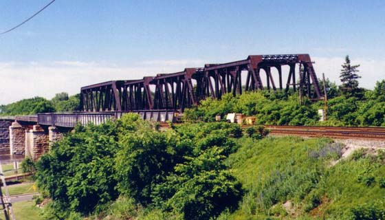
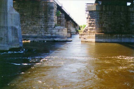
At Ste. Anne the line crosses a branch of the Ottawa River flowing between the Island of Montreal at Ile Perrot, by a bridge parallel to, and 61 feet distant, centre to centre, from the Grand Trunk Ry. bridge. The bridge consists of two abutments and thirteen piers of masonry, and fourteen girder spans of steel. Beginning at the east end, and measuring from centre to centre of piers, the first three spans are 104 feet 9 inches each. These are lattice "through" girders, the object being to give as much head-room as possible over the canal locks. The fourth span is 321 feet, and the girder a pin-connected through truss of the most modern American design. The corresponding span on the G.T.Ry. bridge is only 220 feet, owing however, to the obliquity of the current in the river at this point and the consequent danger to descending rafts, the Department of Railways and Canals required, that in the new bridge there should be no pier in the stream opposite to No. 4 of the G.T.Ry. bridge. Consequently pier No. 4 of the new bridge corresponds with No. 5 of the G.T.Ry., and there is one span of the former to two of the latter. The 5th span is 101 feet 4 inches, and the 6th 100 feet 9 inches, both being lattice "deck" girders. The remaining eight spans are 66 feet 11 inches each, and are plate "deck" girders. The East abutment is built directly on solid rock, which was found at a depth of 2 or 3 feet below the surface of the ground. The rock here is the Potsdam sandstone overlaid in the immediate vicinity by Trenton limestone. It is of the latter stone that the whole of the masonry is built. At pier No. 1, which comes between the public road and the new lock, the excavation was carried down about eight feet below the surface, at which depth solid rock was found sloping to the S.W., at an angle of about 15 degrees. Convenient fissures in the rock enabled a trench to be formed a couple of feet deep and about the same in width, along the axis of the pier, in order to provide against the possibility of the pier sliding on the rock. Concrete was then deposited in this trench, and brought up level to the height of the highest point of the rock, the masonry being started on the base thus formed. Pier No. 2 came between the old and new locks, and the excavation for the foundation encountered a puddle trench and its cribwork backing, that was formed to exclude the water from the works of the new lock constructed in 1882. This puddle trench, as well as a quantity of cribwork, had to be removed in order to reach a solid foundation. The last foot or two of the excavation being under water was finished by the aid of a diver, and at about 15 feet below the surface of the ground, the solid rock was struck, lying with but a slight fall to the S.W. After the surface of the rock had been thoroughly cleaned off by a diver, it was covered by a bed of concrete about 5 feet thick and about a foot larger each way than the bottom course of the masonry. The first stone of the bridge was laid in this pier on the 3rd of August.
The excavation was carried down to water level in the ordinary manner without much trouble. To continue the excavation below this level it became necessary to remove some forty feet in length of the cribwork in the river front, permission to do this having been obtained from the Department of Railways and Canals. A dredge was then brought up and fixed in position in the river abreast of the pier site, the excavation being by means of it carried down very nearly to solid rock. Owing however, to the proximity of lock tile wall, the dredge had to work with extreme care, in order to avoid disturbing its foundation. As soon as the dredge had done as much of the excavation as could be safely and conveniently done by it, three divers were sent down to complete the cleaning of the bottom, and a bottomless rectangular caisson 34 feet long and 13 feet wide was framed in position of whole timbers 12 inches square. The object of this caisson was to prevent the sides of the excavation from filling in and covering the site of the pier, as well as to form a mould for the bed of concrete. By means of accurate soundings, the caisson was framed as nearly as possible to conform on the upper side to the irregularities of the rock and the projections of the lock wall. On the lower, or river side, there was a space beneath the lowest timber of some three or four feet. As soon as the caisson was finally and accurately fixed in position, this space, as well as the small cavities that still remained under the timbers on the upper side, was enclosed by driving 3 inch planks around the outside of the caisson and spiking it firmly to the timbers. Inside the caisson as now fixed and enclosed, three divers continued and completed the final cleaning of the bottom, about ten days being occupied by this work. When this was satisfactorily accomplished, a bed of concrete, varying from 5 to 9 feet in thickness, was deposited within the caisson by means of a square box of 3/8 inch boiler-plate holding a cubic yard, the bottom of which was hinged in two flaps and adapted for tripping, the scow carrying the derrick that raised and lowered it, and on the deck of which the concrete was mixed, being in the old lock immediately abreast of the pier. The top of the concrete was levelled up and finished to a height of about 6 inches above low water, and eleven days later the masonry was begun. Pier No. 4 is the first river pier, the site being bare rock and the water about four feet deep at lowest level. The caisson for this pier was framed to half its height at a convenient spot on the river bank below the bridge, and then towed up-stream by a tug, and lowered into position. On reaching the site of the pier, it was rigidly held in place by anchors at bow and stern, and the remaining height of timber was added. A bed of concrete, about 2 1/2 feet in depth, was then deposited in it, and as soon as this had set sufficiently the water was pumped out and the masonry commenced. This pier, as well as No. 5, is built on a skew of 10 degrees 30 minutes, i.e., the axis of the pier makes an angle of 79 degrees 30 minutes with the centre line of the bridge. The 5th and 6th piers were built in a precisely similar manner. The water was of about the same depth, and the bottom also bare rock. At piers 7 and 8, the water being less than 2 feet deep, caissons were not necessary, the water being excluded from the foundations by means of plain rectangular cofferdams of square timber built round the site. These were surrounded by a low wall or bank of puddle and then pumped out. All the excavation necessary, consisted of the removal of about a foot of loose and shattered surface rock. At pier 7, no concrete was necessary, the masonry being laid directly on the rock. At No. 8, the rock after being stripped of the loose surface was covered or levelled up with a bed of about a foot in thickness. Piers 9, 10, and 11 are situated on a low rocky island, the surface of which is from one to two feet above low water level, none of them required either caisson or cofferdam. No. 9 has no concrete under the masonry, while at 10 and 11, after stripping the loose rock from the surface, the bottom was merely levelled up with it. Piers 12 and 13 coming in a foot or two of water, required cofferdams and a thin bed of concrete to level up with, At the West abutment, the rock, which was covered with some three or four feet of soil and loose material, was found to dip to the North at about the same angle as it did to the South at the East abutment. It was benched to receive the masonry, and no concrete was used. A small bridge across a creek between Ste. Anne and Vaudreuil, consists of two spans of lattice deck girders 100 feet 9 inches each, the masonry comprising two abutments and one pier. These were built on solid rock, and present no features of special interest. The pier required a cofferdam, and the rock under it was levelled up with about a foot of concrete, none being used in the abutments. At Vaudreuil the line crosses another branch of the Ottawa, flowing between Ile Perrot and the main land. The bridge here is parallel to, and distant 67 feet, centre to centre, from the Grand Trunk Ry. bridge. It consists of two abutments and sixteen piers of masonry with seventeen spans of steel "deck" girders. Beginning at the East End and measuring from centre to centre of piers, the first eight spans are 100 feet 9 inches each, lattice girders, the next seven spans are 71 feet 21 inches each, plate girders, the remaining two are 65 feet each, also plate girders. The East abutment stands just above low water mark. Its foundation was carried down to a hard bottom of stoney clay at about 5 feet below the surface. The first seven piers, and the sixteenth, were built in water varying from 8 to 20 feet in depth. The first operation in their construction, after having closely covered the site of each pier with accurate soundings, was the removal of the gravel, mud, and boulders overlying the rock, which was accomplished by an ordinary floating steam dredge anchored over each foundation in succession. Bottomless caissons built of 12 inch square timber, and pointed at bow and stern, were then towed into place, their exact positions being determined by means of two transits, one on the centre line of the bridge on shore, and the other on the G.T.Ry. bridge in the line of the axis of the pier produced. They were then firmly held in place by suitable and sufficient anchors, and weighted until they rested on the bottom. Very accurate and careful soundings having been taken over the exact sites of the piers subsequent to the operation of dredging, the bottom (i.e., the bottom edges) of the caissons were framed to fit the irregularities of the rock. As soon as they were in position, the bottom, within their area, was thoroughly cleaned by divers of all gravel and small boulders left by the dredge, any crevices between the bottom timbers and the rock being tightly packed with pea-straw. A depth of concrete equal to about one-third of the depth of water was then deposited with them by means of the iron box, and the surface of this bed levelled up by the divers. When the concrete had set the caissons were pumped out by a 6 inch centrifugal pump, driven by a floating engine of about 15 horsepower, and the masonry commenced. In one or two instances when the water was nearly all pumped out the bed of concrete was burst upwards by the pressure from below. When this happened, the caisson of course filled immediately, and it became necessary to send down divers to repair the leak, additional concrete also being put in for the purpose. Piers 8 to 15 inclusive, being in shallow water, required no caissons. The foundations were surrounded by cofferdams built of large flatted timbers, sheeted outside with 3 inch plank and with well rammed puddle walls all round. After the spaces enclosed by these water-tight dams were baled out, the excavations were carried down to the necessary depth with pick and shovel, and the masonry built directly on the hard bottom without the use of concrete. The West abutment, like the East one, was built just above low water mark. A solid foundation of hard-pan was reached at a depth below the surface of about 8 feet. The whole of the masonry was finished about the 1st June, 1887. The concrete used in these bridges was composed of Portland cement, sand, and limestone broken to pass through a 2 inch ring. It was mixed in the proportions of 1 volume of cement, 1 of sand, and from 4 to 5 of broken stone, which made an exceedingly rich concrete. In fact, generally the beds upon which the masonry was built were almost as hard as the stone itself. A less expensive composition in the foundations would have easily and safely carried all the weight they were called upon to bear, but one of the objects in making the concrete so rich was that it might be capable of withstanding the strain of the upward pressure of water, due to the difference in level between the outside and inside of the caisson. This was occasionally considerable, in some cases being as much as 800 pounds per square foot, and consequently any economy effected by stinting the cement, would probably have been sunk by the additional expense of repairing leaks, and by the loss of time in extra pumping. The concrete was mixed on a decked scow anchored alongside the caisson, In the centre of the scow was a pile of broken stone, and at each end a number of barrels of cement and a pile of sand, leaving a clear space on each side of the pile of broken stone. A barrel of cement being broken open, the contents were spread out in a layer five or six inches thick, an equal quantity of sand was then added, and the whole intimately mixed in the dry state with shovels and hoes. A sufficient quantity of water was than poured into the centre of the mass, which was immediately worked into a moderately thin mortar. The broken stone was then thrown in from the heap, the quantity being so regulated that each fragment of stone was completely covered with, and imbedded in, the mortar. The whole heap, after it was thoroughly incorporated, by being turned over two or three times with shovels, was then thrown into the box which it just filled. While at one end of the scow the concrete was being mixed, at the other end it was being thrown into the box and deposited in the caisson. Two gangs were thus kept constantly going and no time lost. The contractors for the whole substructure of these bridges, were Messrs. Wm. Davis & Sons of Ottawa. The temporary staging for the erection of the superstructure of these bridges was of the ordinary character of trestle-work, consisting for the most part of four post bents at spans of about 14 feet, with the exception that for the fourth span (324 feet) of the Ste. Anne bridge, it was all erected in the winter, and calls for no special description. Owing to unforeseen delay in the shipment of the 324 foot span from Glasgow, where it was made, the false work for it could not be erected during the time of low water in the winter. When at length the iron did arrive further delay was caused by having to wait till all the ice had broken up and gone down the stream. In consequence, the false work for this span, commenced May 5th, 1887, had to be erected when the river was at its highest and the current at its swiftest, the depth of water at the deepest point of the channel being 37 feet, and the current from 7 to 8 miles per hour at a considerable skew. Preparatory to framing the bents accurate soundings were taken at the position of each post by means of lengths of gas-pipe steadied by lines to bow and stern of a scow, which was held in place by wire cables to the cribs described further on. The bents were 13 feet apart, those under panel points, i.e., every alternate bent, had five posts each, the intermediates three each. They were framed on a large scow lying alongside the upper canal pier. Before sending any of them down to their place, two small but heavy cribs, about twelve feet square in plan and six or eight feet high, were framed, loaded with stone, and sunk in the stream some four or five hundred feet above the bridge. In addition to these anchor cribs, two tugs were employed during the greater part of the time that this span of false work was in course of erection. As each bent was framed, the scow carrying it was lowered down stream into position, escorted by a tug, and steadied by wire cables to the anchor cribs. On reaching the site the lines to the cribs were made fast and the scow firmly held. The bent was then raised with suitable tackle by two small engines, one on top of each of piers 3 and 4, wire cables having first been made fast to the feet of the posts and carried up to the anchor cribs. As the posts in the channel bents were from 35 to 70 feet long, the current from 7 to 8 miles per hour and the water 60 feet deep, as has been said, it will readily be seen that the difficulties to be overcome in the construction of this temporary staging were of no ordinary character. In one or two instances the posts, upon feeling the force of the current, began to swing, the bracing gave way, and the whole bent had to be dropped into the stream to save the scow from being broken to pieces by the lashing backwards and forwards of the lashing posts as the motion increased. A tug was then despatched to pick up the posts and tow them up the canal to be re-framed. Immediately upon each bent reaching a vertical position, it was promptly steadied from the water line to the tops of the posts, a height of about 30 feet, by braces and waling pieces of 6 inch x 10 inch stuff bolted and spiked to the last preceding bent. Owing to the utter impossibility of ascertaining to a few inches the exact depth of water in which each post would stand, the braces and caps were all double, and attached to the bent by bolts passing through them, but not through the posts, thus leaving the latter free to move up and down to a small extent to suit the inequalities in the bottom. In addition to the wire cables attached to the feet of the posts, and as a further precaution against slipping, they were furnished with a heavy pointed spike bolt driven into the timber. The last bent was successfully placed in position on the 27th of June, the "traveller" was completed on the 29th, and the erection of the span commenced on the 30th. Superstructure. The following table gives the more important particulars of the superstructure of the three bridges:  The whole of the spans are of steel, were built under the direct supervision of the Company's inspector. The contractors for the work were the Union Bridge Co. of New York. The sub-contractors who actually built the spans were as follows: For the 324 foot span, Arrol Bros. Glasgow (except for the eye-bars, which were made at the Union Bridge Company's own works in Buffalo). For the 104 foot 9 inch spans, The Horsely Co., Tipton, Staffordshire, England. For the 101 foot 5 1/2 inch and the 10 foot 9 inch spans, The Cleveland Bridge Co., Darlington, England. For the 71 foot 2 1/2 inch, 6 foot 1 inch, and the 65 foot spans, Arrol Bros., Glasgow. The cost of the bridges is given in the following statement: Ste. Anne Bridge $185,206.58 During the progress of this work, there occurred two fatal accidents. On Friday, January 21st, 1887, Mr. Harold W. Keefer, M. Can. Soc. C.E., Assistant Engineer, while in the discharge of his duties, fell from the top of the girders of Vaudreuil Bridge, a height of about twenty-one feet. He struck his head and shoulders, the blow causing concussion of the brain, from which he died at half past six the following morning. Mr. Keefer was 29 years of age, a son of Mr. T.C. Keefer, C.M.G., Past-President Can. SoC. C.E., and an engineer of marked ability and great promise. The author is glad of this opportunity of recording the highest, appreciation of his excellent qualities. As an engineer he was well up in his work, active, energetic, and thoroughly devoted to duty. Of sterling worth as a man, he, in every respect, commanded the highest regard and esteem of all who knew him. Generous, open-hearted, and the soul of honour, he was, in a word, his Either's son. On the 30th April, during the erection of the false work for the long span at Ste. Anne, a scow with five men on it, while being towed up stream by a tug, capsized in the channel just above the bridge line. Four of the men were rescued by boats from the shore, but the fifth, a young man by the name of Rodgers, from Glasgow, an employee of the Union Bridge Co., sank before help reached him. His body was recovered about a week later. The chief engineer of the above work was Mr. P.A. Peterson, M. Can. Soc. C.E., the resident engineer being Mr. C.E.W. Dodwell, M. Can. Soc. C.E. Editor's Note: Individual bridge cost breakdowns, a discussion, extracts from general specifications, and the appendix were omitted from this article for brevity. 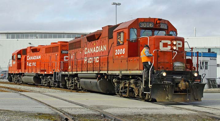 Canadian Pacific 3006 and 3001 switching Univar Canada Limited on the Van Horne Lead - 5 Mar 2014 Andy Cassidy. Vancouver British Columbia - This set of photos is a compilation of four separate photo shoots highlighting the CP Van Horne Spur and Lead. The first one from back in July 2010 and the last being 5 Mar 2014. I've only attached a handful of the total batch of photos here for direct viewing just to give you an "Executive Summary". The CP Marpole Spur currently runs from Mile 16.2 in New Westminster to Mile 6.2 in South Vancouver (Marpole), where it ends active territory at Hudson Street. The line carries on Northward in Vancouver to Mile 0.0 along the Arbutus corridor, but has been out of service there for years now. In addition to this are the operations South of the Fraser River in the city of Richmond. This segment is the Van Horne Spur and Lead, and starts at the Marpole Bridge (Mile 6.3 on the Marpole Spur), and carries on for 1.7 Miles South into Richmond. Once over the Marpole Bridge, the line splits with the Van Horne Lead heading East over to the only customer left in Richmond, Univar Canada Ltd. This is at Mile 0.31 on the Van Horne Lead. The Van Horne Spur past the junction is unused, and slowly over time track has been razed to its current termination point near the Olympic Oval at Gilbert Road. For the longest time I've been wanting to get shots of power traversing the bridge and servicing Univar on the Van Horne Lead. Some of you may recall back in June of 2012 I reported the bridge being pulled out of service due to deteriorating pilings that make up a number of the trestle bents. Rumour had it CP wanted the bridge removed. When it went out of service I thought I was out of luck getting any working photos there. However, Transport Canada ordered it returned to service, so CP had to make some repairs and it was back in service after four long months for Univar. Trucking the raw materials to the plant is just not possible on a long term basis. In any event, I figured I'd better get my rear over there for some pictures. I was told they switch the plant on Wednesdays after 14:00 hours, so we did a dry run on 5 Feb 2014. But before I get into that, let me explain the photo set in sequence. The first photo was taken on 19 Feb 2014 when we took a spin over to Richmond to check out photo spots. There was no activity that Wednesday, but good pictures can be taken from either side of the bridge. Here, I'm East of the bridge on the river Dike looking North and you can see the bridge is open. 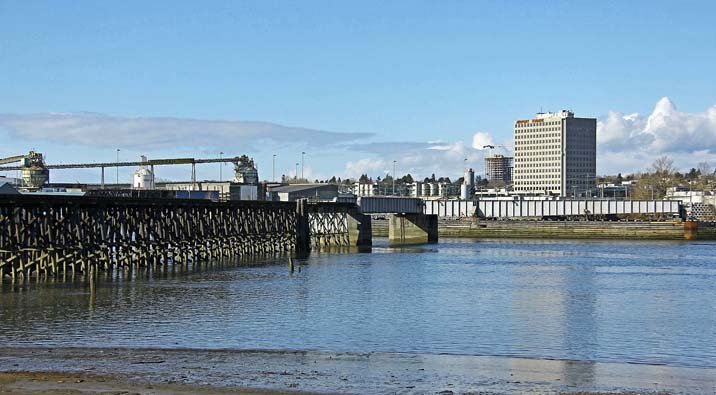 The Marpole Bridge at milepost 0.22 of the Van Horne Spur - 19 Feb 2014 Andy Cassidy. 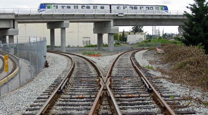 The Van Horne Lead to the left and Van Horne Spur to the right - 1 Jul 2010 Andy Cassidy. Then we go back to 1 Jul 2010. The River Rock Casino/Hotel is right next to the line just off the bridge. We were there for the night and in addition to dinner and some gaming, we walked both the unused Van Horne Spur, and the Van Horne Lead, taking photos along the way. In the photo of the junction, the Lead goes off to the left, and the Spur goes to the right. The new Canada Line Skytrain Maintenance Terminal is to the left and you can see a train on the elevated guide way. 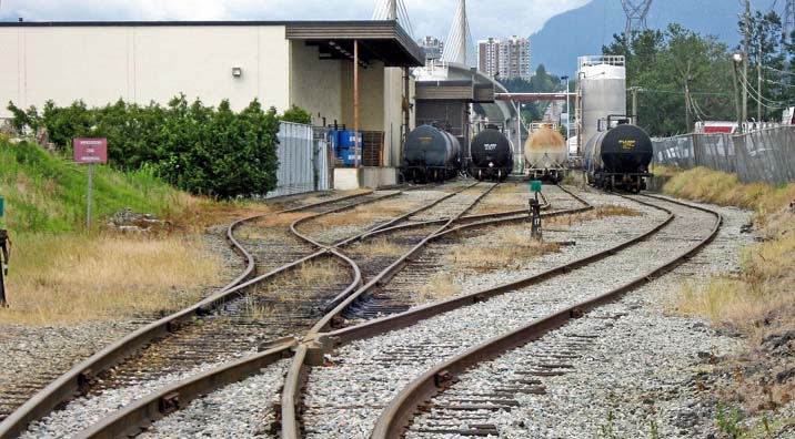 The Univar Canada Limited tracks viewed from their gate - 1 Jul 2010 Andy Cassidy. We carried on along the lead to Univar and there I got a couple of shots of their rail yard from outside the locked gate. They can hold quite a few cars in there when full. These shots were taken with my old Canon A580 Point and Shoot Camera. 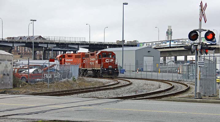 CP 3006 and 3001 switching Univar Canada Limited - 5 Mar 2014 Andy Cassidy. Now that you hopefully have a feel for the area, we go to last Wednesday, 5 Mar 2014. We took a spin down along the length of the Marpole Spur to see if there was any action. Didn't see anything. So we took a spin over the bridge into Richmond, and lo and behold there was a crew switching Univar. CP 3001-3006 (Both GMD GP38AC's), were doing the honours. I found out later they had been there since before noon doing a complicated switch of cars there. So you can see they are working the plant and putting together the empties on track S17 outside the plant. After about 45 minutes, they finally finished the plant moves and brought the power up S18, then back down S17 to get in front of the empties for the trip back to Marpole. Note the nice new paint on the CP 3001. Just came back recently from overhaul at National Railway Equipment Company (NRE) I believe. After backing onto the ten car train, they made their way over the Van Horne Way grade crossing, went around the Skytrain Maintenance Yard and onto the approach to the bridge. It's a pretty good little climb. Those of you looking closely will note the difference in track condition on the West side of Van Horne Way vs the East side of the street. This is because when the Skytrain maintenance yard was built they had to do some realigning of CP track. Consequently, the track coming off the bridge and down the Lead to Van Horne Way is all brand new. Also, the segment of the Van Horne Spur that runs a block or so by the Skytrain Station at the casino is also new, but has never been used to my knowledge. It's all first class track. But once it ties into the original lines, well, you can see the difference. 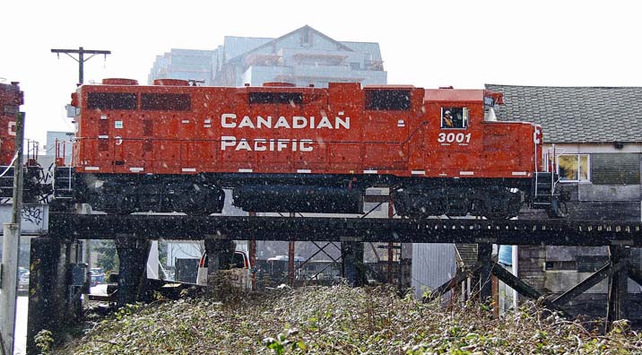 CP 3001 and 3006 cross the approach to the Marpole Bridge at milepost 0.6 of the Van Horne Spur - 5 Mar 2014 Andy Cassidy. So once the train cleared the crossing on Van Horne Way, we jumped in the Escape and quickly drove around the corner to the Dike. Then I quickly climbed up the dike and got set up as the train was on the ramp up to the bridge trestle. Prior to this, there was no rain. Just overcast and sunny breaks. All of a sudden this rain starts hammering down as I'm trying to get shots of the train on the approach to the trestle. The sun was directly in front of me, and this heavy rain happening at the same time. Very bizarre! You can see the effects of this in the three shots taken as he approached and hit the trestle. 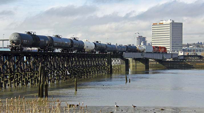 CP 3001 and 3006 cross the Marpole Bridge - 5 Mar 2014 Andy Cassidy. Then, just like that, it stopped. And all the subsequent shots are perfectly clear as he passes over the trestle and onto the swing span and beyond. The last shots of the train going over the bridge gives a pretty good view of the repair work done to strengthen the Bridge Bents on the north end of the bridge. How long they will last, I don't know. 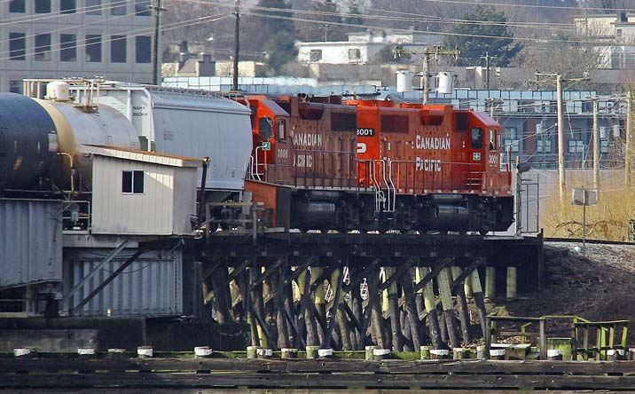 The repair work to the trestle bents of the Marpole Bridge are visible in this photo - 5 Mar 2014 Andy Cassidy. Well, that was it for the day. Andy Cassidy. |