 | Canadian Pacific Odds and Ends - Part 7 Articles |
Fifty-Ton Single Track Coaling Stations - Canadian Railway & Marine World 1921. The "Last Call" page has appeared weekly on OKthePK's web site over the past couple of years. Each week a different article told the story about various railway items of interest. While some of the articles were saved they were no longer available online. Several of those about the Canadian Pacific Railway have been compiled here on this page. There is insufficient room to display more than a few articles per page. As a result, "Canadian Pacific Odds and Ends - Part 7", continues this month with more possible parts to follow as time progresses. Every month they will be archived to the CPR Set-off Siding web site for future online retrieval. Look under the articles section on the CPR Set-off Siding web site to find these archived pages. 
 A number of small capacity coaling stations have been built on the C.P.R. at intermediate points, so that locomotives delayed by adverse weather or other conditions may be re-coaled between terminals. The accompanying cross section shows the general outline and construction quite clearly. The structure consists of an elevated coal pocket, supported on wooden bents, with a coal dump hopper in the rear, and an elevator for the coal conveyor in the center. The coal brought by cars is discharged into the dump hopper, runs by gravity to the receiving boot, where it is picked up by buckets operating on endless chains, and conveyed to the coal pocket above. Where electric power is available, a motor is used for hoisting, and the motor and necessary machinery are housed in the roof of the structure, provision being made for stopping motor on either side of the coal car at track level. Where electric power is not available, a gasoline engine is used, and the house is located at ground level. The capacity of the plant is 50 to 60 tons, and this, with the storage in the hopper, allows for two car loads of coal being on hand for emergencies. A 15 h.p. motor or engine is used for elevating. 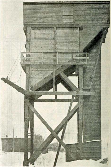 Fifty-ton, Single Track, Electric Drive, Coal Handling Plant, Canadian Pacific Railway, Sutton, Quebec. The dump hopper is elevated 6 feet above the ground line, which is reached by grading the approach track from 2 percent to 5 percent, depending on the amount of room available, and local conditions. The hopper is made long enough to accommodate half a car only, in order to get the floor and sides steep enough to keep the coal moving to the boot under adverse weather conditions. It was found that a hopper large enough to take a full car, would require too much height and depth to get a steady flow of coal, and was too costly to be considered for this size of plant. 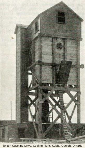 As a further aid to feeding coal to the boot, the sides of the hopper are given a vertical drop at the entrance door, which controls the flow of coal from the hopper to the boot. The dump hopper is protected by a screen, made of old rails, at about 6 inch centers, and is erected on a slant just under the main girders of the coal car track, any lumps failing to pass through the screen are broken on the rails. It has been found that a shelter over the coal dump hopper is an advantage in severe weather, and makes for better working conditions. It usually consists of 6 x 8 inch posts and roof beams, with 2 inch plank covering, and tar and gravel, or ready roofing on top. This is not shown on the accompanying illustrations, as the plants were not completed when the photographs were taken. The pit in which the receiving boot is located is built of concrete and the balance of the structure is wood. The hoisting elevator consists of a straight line of double link belt chain, to which buckets are attached at intervals. At the top of the shaft, the chain and buckets are diverted to travel across the house for a short distance, to enable the coal to be dumped about the center of the pocket. The coal pocket is supported on ordinary frame bents, 3 inch plank is used for the floor, and 2 inch plank for the sides of the pocket. Both floor and side are covered with No. 10 sheet steel lining. The pocket is roofed over, and has sufficient housing overhead to accommodate the shafts, gears, sheaves, and operating machinery. The pocket was first built with one apron, and coal chute door, for supplying the locomotive, but later this was changed to provide two outlets. To facilitate repairs, and the proper maintenance of the door and apron mechanism, a light gallery, with rail, is placed on front of the coal chutes just above the drop doors. A number of these coaling plants have been built by Williams & Wilson, Montreal, who have supplied the two photographs reproduced herewith, illustrating plants built at Guelph. Ontario, and Sutton, Quebec, this company making a specialty of this class of work, and having developed to a high point of efficiency many of the details, such as steel boots, aprons, operating machinery, cut off gates, and the like. It is well known that coaling plants in general are subject to very rough usage, and adverse weather conditions, and for these reasons it is necessary, if the best results are to be obtained, that the operating mechanism be made extra strong, especially in regard to chain and buckets, as well as gears, sheaves, and shafting, and that these, whenever possible, be made interchangeable for all plants, in order to keep down the number of parts to be carried in stock and to facilitate repairs. Canadian Railway and Marine World is indebted for the foregoing information to J.W. Orrock, Principal Assistant Engineer, C.P.R., Montreal, to whom credit should also be given for the design.
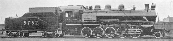 Decapod Locomotive, Canadian Pacific Railway. By J.W. Buckland, Chief Draughtsman, Angus Shops, Montreal.The question of economic and efficient locomotives is one which claims the attention of motive power officials and railway executives probably more at present than at any time in the history of railroading, and what is desired is an engine with maximum tractive effort that can be got over its division with the least possible delay. With this end in view it is imperative that a locomotive should be as simple as possible, both to operate and repair, and that its details should be made as fool proof as possible. The subject of this article is the Decapod type of locomotives rebuilt recently at Angus shops, Montreal, from Mallet 0-6-6-0 type, which had been until recently working on hill service in the Rockies. It was necessary, owing to demand of large power of this kind, to convert these locomotives with the least possible delay, and 30 days from the time the order was given, sketches were completed and work was under way in the shops. The first locomotive was turned out in another 20 days. In a design of locomotive such as a Decapod, with long driving wheel base it is necessary to introduce flexibility in order to insure proper tracking and minimize flange wear. For this reason the leading driving wheels on this locomotive were arranged to give 1 inch side play between shoes and driving box flange. See Fig. 1. 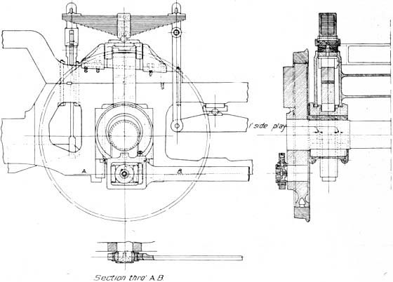 Fig. 1 - Decapod Locomotive, C.P.R. Arrangement of Leading Driving Wheels. Incline planes have been applied over the leading driving wheels, in order to centre them when running on straight track, and the resistance due to weight applied to incline planes, provides guiding power when the locomotive is entering a curve. With the application of the above to a pair of driving wheels it is necessary to provide flexibility to the side rods, in order to eliminate any undue strain to crack pins and rods. The design of flexible side rod connection is illustrated by Fig. 2, from which it will be noted that it is a universal joint in its entirety, the crank pin being one axis of movement, and the brass, being turned on a vertical axis, provides for side sway of the rod. With this arrangement of joint, it is possible to provide a perfect lubrication to the crank pin and it is also simple to machine and maintain in the locomotive house. The arrangement of driving wheel and side rods described above can be applied to any locomotive, with minimum outlay, where trouble is experienced due to flanges cutting. 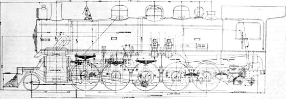 Fig. 2 - Decapod Locomotive, Canadian Pacific Ry. Erecting Plan. Another important feature of this design of locomotive, "which of necessity has long overhang beyond trailing driving wheel", is the location of the drawbar pin on the engine. It will be noted from the general arrangement in Fig. 2, that this pin is located as close to rear driver as possible. This was done to reduce to a minimum the flange pressure of rear wheels when backing into curves. GENERAL DATA Tractive effort ..... 61,500 pounds. CYLINDERS Kind ..... Simple VALVES Kind ..... Piston WHEELS Driving over tires ..... 58 inches BOILER Style, Radial stayed firebox, with cross stays, and conical course. TENDER Wheels, diameter ..... 36 inches The tender is equipped with 45 degree coal space, which eliminates the necessity of fireman having to shovel coal ahead on tender. In converting the tender from 5,000 to 7,000 gallons capacity, the tank was lengthened 6 feet at the back portion and the frame was spliced at the front end, the splice being made to extend beyond the bolster of the leading truck, and the draft gear fastening at the rear was not touched. The engine is equipped with two sandboxes, to insure proper gravitation of sand to desired points. Flange lubricators are applied to front and rear driver. The engine is also equipped with straight line Walschaert valve gear and self centering valve stem guide. The link is supported at each side with bearings on mill plate supports, which also support reversing crank arms. The crosshead arm has been eliminated and the union link is connected to the collar, which is welded to the crosshead thereby making the wrist pin fit independently of the union link bearing. The specialties include: Casey-Gavin reverse gear, McCord force feed lubritor, Franklin butterfly type 8 fire door, Security brick arch. Not included with the original Canadian Railway and Marine World article are these two photos, Canadian Pacific Mallet number 1950 taken at Field in 1910, and number 1955. Also, appearing on several back covers of Canadian Pacific employee magazine, the Spanner, were photos and data of their steam locomotives known as "Collectors' Items". Refer to the Mallet locomotive page and the Decapod locomotive page. 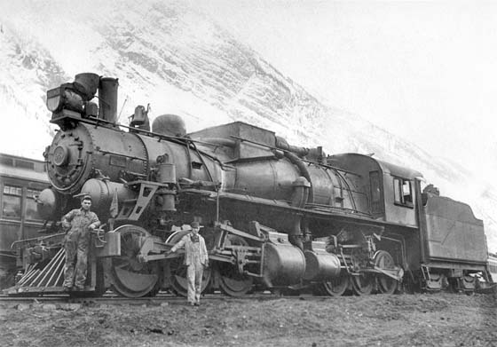 CPR Mallet 0-6-6-0 class R1a number 1950 at Field, B.C. - 1910 Photographer? 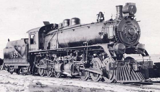 Canadian Pacific Mallet 0-6-6-0 class R1c number 1955 - Date? Photographer?
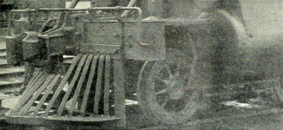 Pilot on Pacific Type Passenger Locomotive, C.P.R. 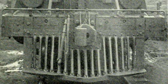 Pilot on Pacific Type Passenger Locomotive, C.P.R. The accompanying illustrations show a standard steel pilot applied to a C.P.R. Pacific type passenger locomotive, which is simple, but strong and inexpensive to manufacture and apply, giving a very neat, substantial appearance. The bars are made of old boiler tubes, which are put through a set of rollers and rolled into triangular shape, so that they resemble the ordinary slat used with a wooden pilot. The rolling is done cold. The bars are flattened and bent at each end to the proper angle to suit their location in the pilot. They are fastened to the pilot frame and nosing by 1/2 inch rivets. The nosing is made of 3 x 3 x 5/16 inches angle, and the frame of flat steel bars. 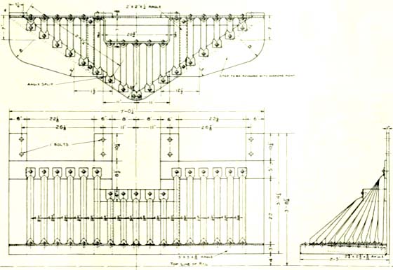 Details of Pilot on Pacific Type Passenger Locomotive, C.P.R.
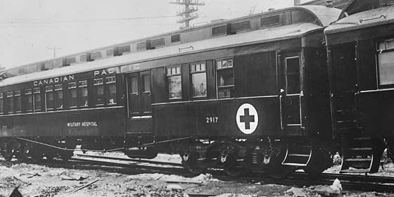 Canadian Pacific Railway Hospital Composite Car - Date? Photographer? The CPR is remodelling eight tourist cars for the Military Hospitals Commission's service in removing wounded and invalid soldiers from the seaboard to their destinations. Four of these cars will be composite, including kitchen and accommodation for medical officer and nurses, and four will be straight ward cars. The cars will be run in pairs, one composite and one ward car. Patients for the ward cars will be taken on and off through the side door entrance of the composite car, and to facilitate this movement, the end doors have been increased to 3 1/2 feet wide at one end of each car only. The cars have six-wheel trucks, steel platforms, and double sash, and are in general conformity with the standard construction of first class tourist cars. The illustration on this page shows plan views of the ward and composite cars respectively. The ward cars have accommodation for 14 patients, and composite cars are arranged with six cots in addition to quarters for medical officers and nurses. The accommodation for the nurses is equivalent to that of a drawing room on a standard sleeping car, and is upholstered in leather. The kitchen accommodation is of the same type as is provided on the standard tourist sleeping car. The medical officers' quarters are arranged in a compartment with upper and lower berths and there is a small dispensary to each car so arranged. The ward cars consist of one large room the length of a standard sleeper, with lavatories at each end. The floors are covered with linoleum and the aisles are carpeted. The composite cars have two side entrances in addition to the usual one, these being utilized for the reception of patients, and the entrance are so arranged that heavy curtains can be drawn closely in bad weather, affording ample protection to patients already in the cars. The cars are lettered on the outside with the words Military Hospital, with a large red cross in the centre.  Hospital Cars, Canadian Pacific Railway, for Military Service.
The accompanying illustrations show how snow was handled in Fort William terminals during the past winter. Fig. 1 shows snow plough and spreader, which means a plough on both ends, and no time is lost in ploughing in either direction, or winging. Fig. 2 shows a champion ice cutter, which clears out all the ice from between the rails, no matter how hard it may be. It is operated by air. Fig. 3 shows a train removing the snow from between the tracks in the terminals. Fig. 4 shows the big lift bridge over the Kaministikwia River, where over 1,500 cars of snow were dumped during the winter. Fig. 5 shows cyclone snow blower for cleaning out loose or soft snow from the switches and leads. This is an invention of D. McIntyre, the Roadmaster of the Terminals. It is an ordinary fan attached to motor car, and having swinging spout so that it can be swung to either side of the track. Mr. McIntyre hopes to improve on this, so as to affect a big saving next winter. 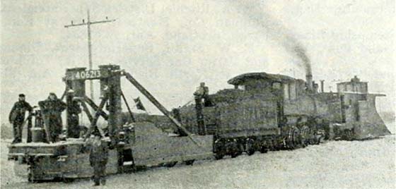 Fig. 1. Snow Plough and Spreader. 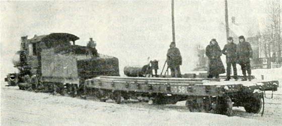 Fig. 2. Air Operated Ice Cutter. 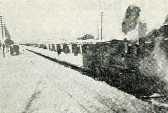 Fig. 3. Removing Snow Between Tracks. 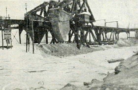 Fig. 4. Kaministikwia River Swing Bridge. 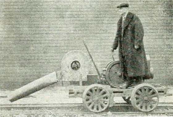 Fig. 5. Cyclone Snow Blower. 
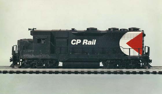 A model shows the proposed 1968 locomotive livery - 1968 Photographer? - CP Rail. From the press kit distributed to hundreds of media around the world in 1968, this photo shows what the originally intended paint scheme was to be on CP Rail locomotives. 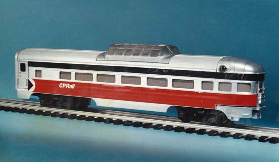 A model shows the proposed 1968 passenger car livery - 1968 Photographer? - CP Rail. Direct from the press kit of 1968 we see what the proposed colour scheme was for Canadian Pacific's (CP Rail) passenger fleet. 
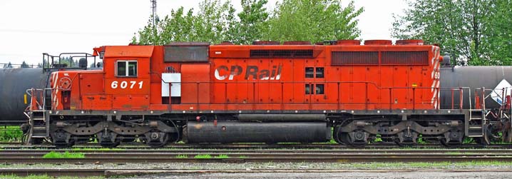 CP 6071 at Coquitlam X-Yard, milepost 111.9 of the Cascade Sub, in Port Coquitlam - 16 May 2011 Andy Cassidy. It was a rainy Monday and for some reason we were over in Port Coquitlam so I passed through the CP yard and caught an oddity at the West end of X-Yard on the North Side of the yard.  This unit, along with a number of others, were set up to be able to provide standby power in the event things went South when Y2K came. Andy Cassidy. 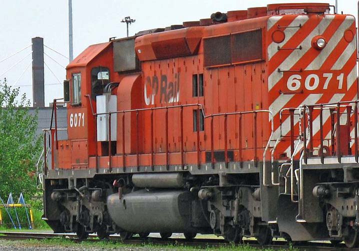 CP 6071 at Coquitlam X-Yard, milepost 111.9 of the Cascade Sub, in Port Coquitlam - 16 May 2011 Andy Cassidy. |