
The provision of suitable locomotives to meet severe and difficult working conditions is always the most fascinating and romantic section of locomotive engineering. I have thought that a brief description of how the Canadian Pacific Railway have met the ever-increasing traffic demands of the last 10 years for adequate power in their Rocky Mountain Section, together with a short description of that Section, would be of interest to the Members of this Society.
I am speaking as a former member of the C.P.R Locomotive Staff, and also as one who has lived for some years on the Western side of the Rocky Mountains, so I may as well admit at the outset that I am an whole-hearted enthusiast on the subject of this paper.
The fact that I am able to illustrate, as well as describe, some of the locomotives constructed by the Canadian Pacific Railway, is due to the kindness of Sir George Maclaren Brown, that Company's European General Manager, Mr. W.H. Winterrowd their Chief Mechanical Engineer, also the Canadian Railway Club of Montreal, to whom my thanks are due for the original photographs and drawings.
First, just a word as to Canada as a whole and as to the extent of the C.P. Railway. Canada is nearly as large as Europe, and has a larger area than the United States. The relative populations are as follows:
Great Britain ... 471 persons per square mile.
United States .... 25    "     "     "    "
Canada ............ 2    "     "     "    "
There is plenty of room in Canada, and 500,000 settlers on the land are now being invited to go there.
Now as to the C.P.R. Its length of direct main line from the:
Atlantic to Pacific ........ 3,740 miles.
Total track mileage ....... 18,250   "
Telegraph wire mileage ... 100,000   "
The City of Winnipeg is about half-way across, and between there and the foot hills of the Rocky Mountains lie about 1,000 miles of prairie land, gently rising from an altitude of 750 feet at Winnipeg to 3,550 feet at Calgary. It is a sight never to be forgotten to pass over this prairie section when the wheat is ripe for reaping and the westering sun gleams tawny gold across millions of acres of ripe grain.
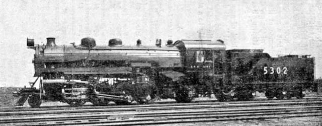
![]() From the East to the Rocky Mountains, the standard passenger engine is of the Pacific 4-6-2 type, and Fig. 1 shows the latest class of this locomotive.
From the East to the Rocky Mountains, the standard passenger engine is of the Pacific 4-6-2 type, and Fig. 1 shows the latest class of this locomotive.
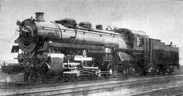
It is claimed that they are the largest and finest 4-6-2 passenger locomotives built up to the present date, and I think you will agree that they look the part. They are two cylinder machines, having cylinders 25 inches in diameter by 30 inch stroke. Driving wheels are 6 feet 3 inches in diameter. Boiler pressure 200 pounds per square inch, superheated. The cylinder tractive effort at 85 percent, boiler pressure is 42,600 pounds. Adhesion factor 4.25. Total weight 133 tons without tender.
The new standard C.P.R. locomotive cab is of considerable interest. As you know, the weather is sometimes as much as 50-60 degrees below zero, and an engine crew therefore need very complete protection in winter, especially when the lonely nature of some of the long sections is taken into consideration. On the other band, the Canadian summer is generally very hot, and enginemen must have as open a cab as possible.
The cab is termed a "vestibule" one. It is completely enclosed on all sides, and is entered through side doors. In the winter therefore it is a snug roomy compartment. In the summer very thorough ventilation is secured through the large side windows and the door openings. We will climb up into one of these comfortable cabs and take a trip over the Rocky Mountain Section of the Railway alongside the enginemen, who, it being mild weather, is seated beside the large open side windows, with the throttle convenient to his left hand and on his right the air-brake valve.
The C.P.R. gradient section across the Rocky Mountains is as follows:

From Calgary (altitude 3,500 feet) the grade rises for 130 miles to 5,321 feet altitude, falls in 50 miles to 2,500 feet, rises in 20 miles to 4,300 feet, falls in 45 miles to 1,500 feet, and from thence undulates for about 100 miles down to sea level at Vancouver. The steepest climb is a rise of 1,133 feet in about five miles, as the crow flies. Parts of the grade here were originally no less than 4.5 percent, but have now been reduced to 2.2 percent by the provision of two spiral tunnels, each about 1 1/2 miles in length.
The Rockies are entered from the East at a point known as "the Gap". The romance of the long search for a practical southerly railway entrance to the Rockies by the pioneer engineers is known to all, and is an epic in the annals of civil engineering, indeed these terrific mountains appear impassible as the train first approaches them, and you realize at once that the locomotives which work across them have got to be some pullers. As the rail tracks lead on, enormous masses of mountains tower on either hand, some black and serrated, others white with eternal snows, or having the brilliant shining green of glaciers on their shoulders. And ever the rails lead onwards, creeping round corners of mountain bastions, along precipice edges, over valleys of profound depths, traversing spider bridges over roaring torrents, or burrowing through spiral grade-reducing tunnels.
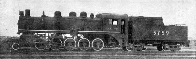
![]() Fig. 2 shows a general type of 2-8-0 locomotive working over the C.P.R. in 1908.
Fig. 2 shows a general type of 2-8-0 locomotive working over the C.P.R. in 1908.
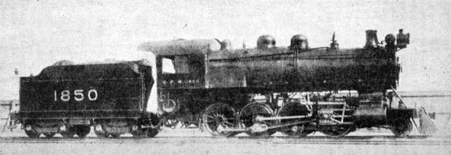
The cylinders are 21 inch diameter by 28 inch stroke. Diameter of driving wheels 4 feet 10 inches. Boiler pressure 200 pounds per square inch. Tractive effort 36,200 pounds. Adhesion factor 4.65. Total weight of engine 185,000 pounds.
In fact very similarly powered engines to the Great Western 2-8-0 machines. These C.P.R. engines were fitted with superheaters, as has every one of their locomotives been since the earliest years of this century.
(It will, I think, interest Great Western men to hear that a somewhat similar experiment to the new G.W.R. 2-8-0 mixed traffic engine, with 5 feet 8 inch wheels, was made by the C.P.R. is 1909. A 2-8-0 engine being then built, having 5 feet 3 inch wheels, cylinders 24 inches by 32 inches, and a boiler pressure of 200 pounds. The tractive effort of this engine was 44,700 pounds, and adhesion factor 4.357.)
In 1900 it became necessary to increase the tractive effort of locomotives working over the Rocky mountains, and Mr. H.H. Vaughan, then Superintendent of Motive Power, decided to ascertain by direct experiment whether a Mallet-Articulated Compound, built to the limits of overall length and weight then allowable on the C.P.R., would be more advantageous for this service than 2-cylinder simple locomotives.
The usual type of Mallet-Articulated engine then being built in the United States was of the 2-6-6-2 type, the rear engine being the high pressure one, and the cylinders of the front low pressure engine being located ahead of the engine. The total wheel base of engine and tender being about 77 feet O inches.
Such an arrangement was at that date impracticable in the case of the C.P.R. for two main reasons:
(1) It would be too heavy for the bridges.
(2) It would be too long to turn on a 70 feet 0 inch turntable.
Mr. Vaughan therefore decided to design a Mallet engine which would both meet C.P.R. conditions as to weight and also turn on a 70 foot table.
![]() Fig. 3 shows how this was accomplished, the resulting engine weighing 117 tons only.
Fig. 3 shows how this was accomplished, the resulting engine weighing 117 tons only.
I was in the C.P.R. Locomotive Drawing Office at that time, and was one of the draughtsmen who were turned on to making the drawings for this engine to Mr. Vaughan's schemes. I think some details of its novel and ingenious construction may be of considerable interest, and I have permission to show these to you tonight.
Fig. 4 shows the boiler of the Mallet Engine.
This, as can be seen, was of a very unusual type. It had three sections:
(1) Boiler proper.
(2) Superheater chamber.
(3) Feed-water heater.
The injectors fed into the front, or feed-water heater section, which, being of small diameter, was always full of water. It will be of special interest to Great Western men to know that the iced water was fed in through check valves located on the top of the barrel. The feed-water section of the boiler had a heating surface of 1,250 square feet.
![]() The superheater had 69 elements each consisting of double loops of 1 1/4 inch steel tubing. These superheater pipes were secured to the headers by union nuts, and so were readily removable for repairs. Also the complete superheater could be easily hoisted out of its chamber through a flanged steel door which closed the top of the latter. It is interesting to note that no cinders were ever found to collect in these chambers.
The superheater had 69 elements each consisting of double loops of 1 1/4 inch steel tubing. These superheater pipes were secured to the headers by union nuts, and so were readily removable for repairs. Also the complete superheater could be easily hoisted out of its chamber through a flanged steel door which closed the top of the latter. It is interesting to note that no cinders were ever found to collect in these chambers.
The Boiler proper appears of unusually short length, nevertheless these engines were remarkably good steamers under all conditions of working. The firebox is large and the grate area 58 square feet. A special point was made of having the internal and external radii of the firebox very large, and the absence of broken stays was specially noticeable with these boilers. The total heating surface of this section of the boiler was 1,555 square feet. The working pressure was 200 pounds per square inch, the highest superheat recorded being 153 degrees in the high pressure steam chests. Two outside 12 inch pipes connect the feed-water section and the boiler proper, one at the side and one on the top.
The throttle valve was located on top of the boiler as shown. It was a casting having two outside 5 inch steam delivery connections. The joint with the boiler was made by a brass ball ring having a 12 3/4 inch inside opening to boiler. Steam was taken from a small steam dome from which the drypipe led to the throttle valve.
The two 5 inch outside steam pipes from throttle led:
(a) As first built, direct to High Pressure (H.P.) cylinders.
(b) As finally decided, to superheater and thence to H.P. cylinders.
All of this piping is, of course, high pressure, but presents no complications as, so far, the engine is rigid and there is no pipe movement.
Fig. 5 shows the cylinder arrangement.
![]() The H.P. cylinders had inside admission valves, exhausting (partially through the valve as a pipe) into a common header, bolted across the front ends of the H.P. cylinders, as shown, and from which a 7 inch pipe led (as the engine was first built) to the superheater. This latter thus acted as a re-heater for the H.P. exhaust which was by this means reheated to a temperature of about 440 degrees, the average pressure being 75 pounds per square inch, (120 degrees superheat) in the L.P. Steam chests.
The H.P. cylinders had inside admission valves, exhausting (partially through the valve as a pipe) into a common header, bolted across the front ends of the H.P. cylinders, as shown, and from which a 7 inch pipe led (as the engine was first built) to the superheater. This latter thus acted as a re-heater for the H.P. exhaust which was by this means reheated to a temperature of about 440 degrees, the average pressure being 75 pounds per square inch, (120 degrees superheat) in the L.P. Steam chests.
After a series of experiments the superheater was finally connected up between the boiler steam and the H.P. cylinders, and the H.P. exhaust steam led direct to the Low Pressure (L.P.) cylinders.
It will be realized that, in either of the above arrangements there had to be an L.P. pipe movement, owing to the articulation of the engine, and this was accomplished in the simplest possible manner by making this joint a plain swivelling one, immediately above the articulated pin. This joint was packed with alternate cast-iron and white metal rings, and was the only packed joint in the steam piping.
A second cross-header was bolted across the rear ends of the L.P. cylinders which latter had external admission piston valves (which also acted as steam pipes for the front ends of the L.P. cylinders).
It will have been noted that, so far, the steam piping has been accomplished with the introduction of a single joint only, and that of the simplest possible description.
Now as to the L.P. exhaust piping:
![]() The L.P. exhaust pipe leads from the cylinder casting along the centre line of the engine and curves up under, and into the smoke-box, as shown in the diagram. Both ends of this pipe have ball ring joints, and both ends have a small rotary movement, but as the angular movement is only 2 minutes 30 seconds on a 20 degree curve, the pipe extension is only 3/8 inch, which is easily taken up by the sliding of the pipe flanges across the flat faces of the ball rings. These flanges are held to their seats on the ball rings by ten helical springs each producing a pressure of 200 pounds. The extension due to the front engine movement being thus provided for, there is no need for any packed expansion joint. The dotted lines show the movements of the pipe on a 20 degree curve, while the diagram at the bottom shows the greatly increased pipe movement which would have occurred had the L.P. cylinders been at the front of the engine. Comparing the two alternative piping arrangements, it will be observed that, with the L.P. cylinders located at the front of the engine, the angular movement of the exhaust pipe would have been 15 degrees 19 minutes on the 20 degree curve, and the L.P. exhaust pipe extension 1 5/8 inches, which would have necessitated the use of two universal ball joints with packing, and also a packed expansion joint to take up the sliding movement.
The L.P. exhaust pipe leads from the cylinder casting along the centre line of the engine and curves up under, and into the smoke-box, as shown in the diagram. Both ends of this pipe have ball ring joints, and both ends have a small rotary movement, but as the angular movement is only 2 minutes 30 seconds on a 20 degree curve, the pipe extension is only 3/8 inch, which is easily taken up by the sliding of the pipe flanges across the flat faces of the ball rings. These flanges are held to their seats on the ball rings by ten helical springs each producing a pressure of 200 pounds. The extension due to the front engine movement being thus provided for, there is no need for any packed expansion joint. The dotted lines show the movements of the pipe on a 20 degree curve, while the diagram at the bottom shows the greatly increased pipe movement which would have occurred had the L.P. cylinders been at the front of the engine. Comparing the two alternative piping arrangements, it will be observed that, with the L.P. cylinders located at the front of the engine, the angular movement of the exhaust pipe would have been 15 degrees 19 minutes on the 20 degree curve, and the L.P. exhaust pipe extension 1 5/8 inches, which would have necessitated the use of two universal ball joints with packing, and also a packed expansion joint to take up the sliding movement.
The receiver pipe movement would have been much the same and this pipe is usually given flexibility by one packed ball joint and one packed expansion joint when the L.P. cylinders are at the front of the engine.
From the above, and the diagram, it will be noted that, had the L.P. cylinders been placed in front of the engine, and following the usual pipe arrangements, five packed joints would have had to be used as against the one required on the engine under review.
Regarding the Walsehaert valve gear, there is nothing particular to mention, except that the L.P. radius bar lifting link is, made very long to minimize the altered L.P. valve travel brought about when the engine is curving. The maximum boiler swing is 9 inches off the centre-line of the front engine and tends to shorten the L.P. valve travel when that engine is in forward gear, and vice versa.
Provision was also made for varying the cut-off in the L.P. engine without altering that of the H.P. engine (this was done by having a slot in the H.P. radius bar lifting arm).
![]() Fig. 6 shows the arrangement devised to take care of the engine when curving.
Fig. 6 shows the arrangement devised to take care of the engine when curving.
As previously explained, one of the main objects in the design of this engine was to keep it of short overall length and that therefore the customary leading 2 wheel truck was omitted. It was felt that the L.P. engine itself, swinging about its rear articulated pin, should adequately provide all the guiding necessary.
The construction and action of the centring and guiding device illustrated were as follows:
The boiler, which offers the principal resistance to curving, was supported on the front truck (which swings laierally under it) partly by friction plates, and partly by a spring suspended roller.
Referring to the drawing. There are two main castings, one mounted on the frames, and the other rigidly supported by the boiler. The weight of the boiler at this point was 40,000 pounds and one-half of the weight was carried on the two radially-curved friction plates shown. The total area of these plates was 834 square inches, and they were lubricated by having oil grooves cut in them.
The resistance due to friction alone as the engine starts to curve is 1,600 pounds.
In the space between the two friction plates is the roller path, which consisted of two inclined planes rigidly secured to the boiler casting. These wedges have their thin ends terminating about 2 inches on either side of the engine centre-line and their inclination is 3/4 inch in 12 inches.
![]() The roller, across which these inclined planes moved as the engine curves (either to one or other side), is carried by two equalizing double-arms, as can be seen in the drawing. These arms being in turn supported by the long spiral springs bearing on the frame-carried casting.
The roller, across which these inclined planes moved as the engine curves (either to one or other side), is carried by two equalizing double-arms, as can be seen in the drawing. These arms being in turn supported by the long spiral springs bearing on the frame-carried casting.
Any movement of the front truck sideways, causes the inclined plane on that side to force the roller downwards against the resistance of the spiral springs and this produces a force which pulls the boiler round the curve along with the front truck, and relieves the leading flanges of the rear truck from the excessive pressure which would otherwise be set up. The arrangement also provides the necessary centering action when the engine again reaches the straight.
This rolling resistance commences at the bottom of the wedges, or 2 inches from the centre-line of the engine on either side, rises at once to 1,250 pounds, and increases to a maximum of 1,965 pounds. at the maximum point of sideways-movement of the front truck.
The frictional resistance slightly decreases, as the weight on the friction plates is gradually lessened by being transferred to the roller, while the resistance offered by the latter could be changed very readily, if desired, by altering the inclination of the wedges or by screwing up the roller supporting springs bottom nuts.
This has the effect of increasing the weight on the roller and decreasing the weight on the friction plates, or viceversa.
Various tests were made on the first of this series of engines. The following are some of the most interesting results:
The flange wear after 4,000 miles running was 3/64 inch on the leading wheels and 1/32 inch on the others. This was satisfactory. The Mallet locomotive curved easier and did less damage to the rails than the ordinary 2-8-0 engines. The many curvatures which have to be traversed in regular working are from 18 lo 10 degrees.
The cylinders of the first engine were fitted with removable bushes, and the following results were obtained from 6 groups of tests:
![]() Indicator cards representative of the important experimental changes made in the engine during tests are shown in Fig. 7.
Indicator cards representative of the important experimental changes made in the engine during tests are shown in Fig. 7.

TEST GROUP No. 1 - The size of the cylinders in the first instance were H.P. 22 inches and L.P. 32 1/2 inches by 26 inch stroke, or a ratio of 2.18.
With these cylinders, and the H.P. exhaust passing through the re-heater, it was found that the L.P. cylinders were developing considerably greater horsepower than the H.P. ones. The former doing 42 percent of the work and the latter 58 percent. This was probably partially due to the increased volume of steam going to the L.P. cylinders, owing to its being reheated and consequently expanded en route, and causing excessive back pressure on the H.P. pistons. This is indicated by the H.P. back pressure being higher than the L.P. initial pressure, as shown on the diagram. The tractive effort averaged 45,500 pounds.
TEST GROUP No. 4 - The diameter of the L.P. cylinder was increased to 34 inches, or a ratio of 2.38. The re-heater was left connected to the H.P. exhaust. With this alteration in L.P. cylinder diameter, the work was much better divided between the two engines, 48 percent being done by the H.P. engine and 52 percent by the L.P. one. The tractive effort then averaged 46,500 lbs.
TEST GROUP No. 5 - The re-heating of the H.P. exhaust was then discontinued and the boiler steam superheated before passing to the H.P. cylinders. The cylinder ratio remaining at 2.38. The division of work between the two engines remained much as in the last test, but a tractive effort of 52,000 was recorded.
TEST GROUP No. 6 - The previous tests showed that with a cylinder ratio of 2.38 the engines were very well balanced in power output. It was, however, desired to get the most power possible out of the engine, and, the factor of adhesion still being high, it was decided to increase the size of the H.P. cylinders. These were therefore increased from 22 inches to 23 1/2 inches in diameter, but it was not possible to bore out the L.P. cylinders any larger. The cylinder ratio now therefore became 2.18, the superheater being left connected between the boiler and H.P. cylinders. The division of power between the H.P. and L.P. engines was now 45 percent and 55 percent, respectively, and a tractive effort of approximately 54,000 pounds was realized with a 1,140 ton train on a gradient of 1 in 65. (1.5 percent)
![]() The locomotive was then put into pusher service in the Rocky Mountain section of the railway.
The locomotive was then put into pusher service in the Rocky Mountain section of the railway.
The full summer rating over the section of the Rocky Mountains worked by these Mallets was, with the ordinary 2-8-0 engines, 424 tons. The maximum grade being 1 in 45 (2.2 percent). The Mallets were designed to take 660 tons over this section, and in practice it was found that they could take 700 tons comfortably. The maximum tractive effort actually exerted by them in practice being 57,400 pounds.
The coal used is mined in the Rocky mountains and is very dusty. The Mallets steamed well with it, however, the blast pipe orifice being 4 3/4 inches. Owing to the long length of the exhaust pipe the exhaust was very mild.
Six of these Mallets were constructed and they handled the traffic over the section until 1916.
The maintenance of these double engines was, however, high for their power. Also the necessity for having considerable lengths of exposed steam piping in a Mallet locomotive proved an undesirable feature in the extremely cold weather experienced in the Rocky Mountains.
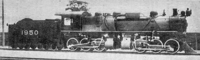
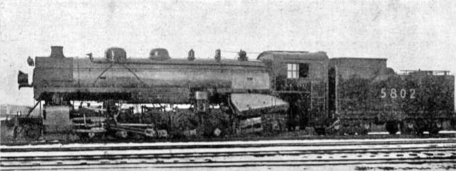
![]() In 1917, therefore, when the demand for increased power on the Rocky Mountain Section again became insistent, 35 engines were constructed of the 2-10-0 type as shown by Fig. 8.
In 1917, therefore, when the demand for increased power on the Rocky Mountain Section again became insistent, 35 engines were constructed of the 2-10-0 type as shown by Fig. 8.
These engines have 2 simple cylinders, 24 inch diameter by 32 inch stroke. The boiler pressure is 200 pounds per square inch, and the steam superheated. The driving wheel diameter is 4 feet 10 inches and the tractive effort 54,100. Nearly the same tractive effort as the Mallets was therefore attained in these engines, which weigh 112 tons.
Last year it was decided to see whether still greater power could not be satisfactorily obtained from a suitable unarticulated engine, and the present Chief Mechanical Engineer of the Company Mr. W.H. Winterrowd, has designed and constructed at the Company's Shops at Montreal, 15 Santa Fe, or 2-10-2, locomotives as illustrated in Fig. 9. These are the most powerful engines which have been put into Canadian Railway service up to date and they weigh 158 tons.
They have 2 simple cylinders of 26 1/2 inches diameter and 32 inches stroke. The boiler pressure is 200 pounds to the square inch, and the steam superheated. The driving wheel diameter is 4 feet 10 inches. Their tractive effort at 85 percent boiler pressure is 65,870 pounds, and the adhesion factor 4.18.
![]() Up to date these fine locomotives are doing all that can be put onto them by the Operating Department over the Rocky Mountain section of the railway.
Up to date these fine locomotives are doing all that can be put onto them by the Operating Department over the Rocky Mountain section of the railway.
From 1908 to 1921, three things have remained constant for all C.P.R. locomotives working on the Rocky Mountain section, namely:
(1) The driving wheels have all been 4 feet 10 inch diameter.
(2) The Boiler Pressure has been 200 pounds per square inch.
(3) All engines have been superheated.
The tractive effort has however progressively increased from 36,200 pounds to 65,870 pounds (or 80 percent), while cylinders have grown from 21 inch diameter by 28 inch stroke to 26 1/2 inch diameter by 32 inch stroke, or an 81 percent increase in volume. These figures are an eloquent tribute to the progress which has bean made in modern locomotive boiler design. It is now six years since I was in Canada. I fear I have given you but a meagre impression of the awe-inspiring and terrific magnificence of the Rocky Mountains, and a very inadequate appreciation of the great locomotives which the genius of the Canadian Pacific Railway has created to conquer them.
It is a spectacle to stir the blood of any British railwayman to see the C.P.R. "Transcontinental", all dusty in summer, or snow-coated in winter, and travel-stained after the long 3,750 mile haul across Canada from the Atlantic coast, gliding into the Vancouver terminus and coming quietly to a standstill at the very edge of the wide Pacific.