 | Canadian Pacific Odds and Ends - Part 10 Articles |
Construction of Steel Upper Frame Box Cars - Cdn Railway & Marine World 1914. The "Last Call" page has appeared weekly on OKthePK's web site over the past couple of years. Each week a different article told the story about various railway items of interest. While some of the articles were saved they were no longer available online. Several of those about the Canadian Pacific Railway have been compiled here on this page. There is insufficient room to display more than a few articles per page. As a result, "Canadian Pacific Odds and Ends - Part 10", continues this month with more possible parts to follow as time progresses. Every month they will be archived to the CPR Set-off Siding web site for future online retrieval. Look under the articles section on the CPR Set-off Siding web site to find these archived pages. 
The Construction of By R.W. Burnett, General Master Car Builder, Canadian Pacific Railway.Steel Upper Frame Box Cars 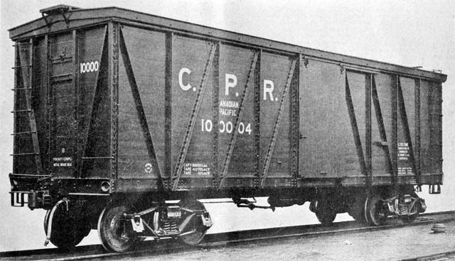 First inside sheathed steel frame box car for Canadian Pacific Railway. (ABSTRACT OF PAPER - This paper outlines the development of the box car from the all wood car to the steel under and upper frame constructions now so exclusively in use, and discusses some of the factors that have been effective in establishing steel frame construction. The advantages of the steel upper frame construction are discussed in particular, and the practice of the C.P.R. in construction and repairing is referred to in detail. The advantages that this type has over the wooden superstructure car, which are of value to the operating traffic and mechanical departments of the railways are enumerated as follows: Low tare weight. Clean inside finish. Ease, with which it can be cleaned and kept clean. Answers the purpose, when built with rolled shapes, of a standard car as regards the low cost of maintenance and small amount of material necessary to keep in stock for repairs, and the fact that repairs can be made by the company on whose line the car is without any special tools or dies. An economical car to build, both as regards size of plant and cost of equipment required. Does not deteriorate more rapidly in service than when idle. Small percentage out of service for repairs. Protection against losses from leakage and damage from weather. Much longer life than wooden superstructure cars. Immunity from serious damage to superstructure in wrecks. Protection to roof due to the stiffness of the superstructure. Minimum clearance at eaves.)  Steel frame of Canadian Pacific Railway box car ready for lining. This paper, which is confined solely to superstructure details of the steel frame box car, is intended to apply in general to steel frame practice as developed in connection therewith. While the early development of steel upper framing is passed over rather briefly, many of the important considerations that have influenced its adoption are discussed in detail, particularly as viewed by the Canadian Pacific Railway. The information and data presented are based on the writer's experience in this railway system in connection with the design, construction and maintenance of 30,000 cars of this type, which represent an investment of $30,000,000. Credit is due to C.A. Seley, Mechanical Engineer, Rock Island Lines, for designing the first outside sheathed steel superstructure box cars that were constructed in large numbers. The introduction of steel into the superstructure of the box car, and the development of the outside sheathed steel superstructure in particular, were discussed so thoroughly by Mr. Seley in a comprehensive paper before the Franklin Institute in January 1910, that I have thought it unnecessary to go over this same ground, but will review only briefly the development of the box car from the all wood car through the intermediate stages of steel underframe cars. The original wooden car, with the single spring draft rigging having the check castings bolted to the sills, gave little if any more trouble than modern equipment, due principally to the shorter trains, lesser density of traffic, and to the use of link and pin couplers which compelled gentler handling of trains than is prevalent today. The steel underframe car was built mainly to secure a stronger centre construction for the attachment of draft rigging and to get away from the trouble caused by wooden sills breaking and splitting, broken draft bolts, etc. While having many advantages over the old wooden car, the steel underframe car developed some troubles peculiar to itself, the most important being due to the fact that the body being carried on a rigid frame and not held together by the strains resulting from its weight, as in the old trussed cars, has a tendency to develop slack in the superstructure. This in turn affects the roof and sheathing. One principal trouble with outside sheathed cars is that, after they have been in service a comparatively short time, the sheathing frequently loosens at the end sill, and at the side sills near the bolsters, with resultant leakage of grain. There were some steel frame box cars built previous to 1909, but the writer has been able to secure data on only the outside sheathed types. Of these, 2,700 were in service on the Norfolk and Western, of which the first 100 were built in 1902, the owners advise they were satisfactory, and the same type has been purchased on subsequent orders. The Rock Island and Frisco lines had in service at that date approximately 5,000 cars similar to the Norfolk and Western, and these also appear to have given satisfaction as the owners have reordered the same type several times. All of these, however, were outside sheathed. and as regards leakage at the sills, had comparatively little advantage over the wooden cars. Recently both of these lines have purchased some inside sheathed cars. In 1908 the C.P.R. designed a steel frame inside sheathed box car. This car avoided the disadvantage of the outside sheathed car which had not been accomplished by the steel frame cars constructed up to that time, and at once obtained a further reduction in weight and provided for cheapness of maintenance by the use of steel superstructure, without the additional lumber required by the outside sheathed car. With practically no preliminary experimenting, 500 of these cars were built and over 30,000 have been built since similar to the first cars, with the exception of several refinements of details, such as corner and door posts, end doors and side plates, and joining of flooring and lining. These changes have not affected the general design of the car, but are the improvements that have been introduced from time to time to reduce weight and simplify the construction. The steel frame outside sheathed car has several advantages over the types previously used, notably in that the tare ton weight is low in proportion to the capacity. There is such a variation in the figures used for the cost of hauling per ton mile, that no attempt is made to say what the saving would amount to, but certainly the advantage of having a car equal, if not superior to other cars in all respects, weighing from 1,000 to 5,000 pounds less, will appeal to all traffic and operating men. Not only is there that much less dead weight to haul when the oar is empty or partly loaded, but additional lading can frequently be carried. The actual limit on the paying load that can be carried in a properly designed car is the total weight on the axles. Thus, a car having 5 inch by 9 inch axles, with such a tare weight that, when deducted from the capacity of the axles, allows the car to be safely loaded to 88,000 pounds could, if dead weight be reduced by 3,000 pounds, safely carry a paying load of 91,000 pounds and retain the same strength. Thus the actual capacity of the car is increased almost 4 percent with a better ratio of paying to dead load. With the wooden superstructure it had been thought necessary to assist the superstructure by heavy roof construction, some going so far as to use different methods of diagonal bracing, but with the steel car it has been found that there is no appreciable local movement of the framing in the heaviest service, which makes a simple proposition of the roof, as it has only to take care of itself. This presents a simpler problem to roof designers, making it possible to design a roof much lighter, without necessity for use of purlins or ridge poles to strengthen the car. It is obvious that unnecessary weight in the roof raises the centre of gravity, and increases the tare weight and cost and has other disadvantages.  Wooden roof section. In explanation of the local movement of this style of framing, it is well to mention tests we have made in jacking up this car, which demonstrated that the car would take a gentle twist from end to end, allowing the bolsters to be slightly out of the same plane horizontally. This twisting was accomplished without any perceptible local distortion of the sides or ends. The capacity for twisting is a condition to be desired as it allows a car to adjust itself to uneven track conditions. In addition to being 5 1/2 inches narrower than the outside of the sheathing of a wooden car, the superstructure of the C.P.R. car is protected by the framing, so that a side swipe that would do serious damage to an outside sheathed car frequently does not touch the lining and is resisted by the framing without damage to the posts or braces. Frequently it is found that a side swipe that would almost demolish the sides of a wooden car only bends the steel framing, and in making repairs, the lining is merely removed, posts and braces strengthened and the original lining replaced, the whole cost being the comparatively small labour charge. Jacking frames are being installed at all of our principal repair points for all classes of steel cars, and while not original with the C.P.R., have been amplified better to take care of steel frame box cars. With these frames, many jobs that would require the car to be cut apart, taking several days, can be done in a few hours without cutting rivets. With modern steel frame cars, these jacking frames are as much a necessity as the blacksmith shop or any other part of the shop. With the outside sheathed car it is difficult to clean a car properly when it is unloaded, on account of grain lodging between the framework. and also on account of the opening where the posts and braces meet at the bottom becoming obstructed, resulting in grain being retained between the sheathing and lining with resultant complaints from shippers. All of this is overcome by the clean joining of the lining and the floor in the steel frame cars, and it is believed a change of this kind would have come years sooner if designers had kept in close touch with service conditions. One advantage of the steel frame car is that outside of possible repairs due to wreck damage and to wear and tear of couplers, wheels, brake shoes and journal bearings, the car does not deteriorate more rapidly in service than when stored. The grading of lumber for use in these cars is an item that has received much consideration. Yellow pine or fir has so far been the principal lumber used, although we have experimented to some extent with spruce. Spruce has the advantage of being lighter, but it seems to be more difficult to dry it sufficiently for this purpose. Great pains have been taken to avoid knots that are too large or numerous, and while it is generally desirable to have lumber as free from knots as possible, I have never, in the inspection of many hundreds of cars, seen where a knot had fallen out. It is, however, desirable to have lumber as free from sap and shakes as possible and thoroughly dry. When the first of these cars were built outside of the C.P.R. shops we had considerable difficulty in getting the lumber properly dried, due to lack of both experience and facilities on the part of the car companies. We have about 3,000 cars on which the lumber has shrunk and given them a bad appearance, but this result was expected, as when the cars were built the lumber was quite green. The sheathing on these cars could be tightened for less than $4 a car, but very few have been tightened, owing to receipt of practically no reports of loss or damage to lading due to the shrinkage, also as they do not frequently reach our main repair tracks, being shopped only for such repairs as wheels, or wreck damage, we have not considered it advisable to shop the cars for a defect which is almost entirely a matter of appearance. The lining shrinks as much in two months of summer weather as it ever will. The lining should not be matched before drying, as it warps and curls, rendering it difficult to make a tight joint. The rough size of lumber should be at least 1/4 inch greater than finished dimensions. In establishing limits for drying lumber no information or data could be secured whatever, and after experimenting we came to the conclusion that a piece of this lining of full cross section, subjected to a temperature averaging 170 degrees Fahrenheit for 96 hours, should not lose more than 6 percent in weight, and that lumber represented by samples losing more than 10 percent must not be used until further dried. The variable condition of the lumber when taken from the yard makes it necessary to use careful judgment as to the length of time it should be kept in the kiln. At the C.P.R. Angus shops this responsibility falls on the wood mill foreman, whose constant attention to this feature makes him the best fitted for the purpose. The average moisture loss reported by the test department for lumber used on cars now building at the Angus shops is 5.25 percent, which shows that we are getting very satisfactory results from the kilns. A number of tests were made last year on lumber taken from the yard. These tests showed a moisture loss of between 25 and 30 percent, which shows the importance of drying lumber properly. The accompanying form is used for reporting results of tests both at Angus and outside shops.  Form used by Canadian Pacific Railway for reports on moisture determination on lumber. Due largely to our insistence, nearly all of the car plants in the country are now equipped with dry kilns, and any possible additional cost of drying lumber in excess of what has been considered good practice in the past would be less than $1 a car. Such drying would make the car side practically the same as one board, so that it is absurd that the possible shrinkage of lumber should be considered as any reason for this type of car not being built. It has been claimed that lumber can be so dried that it will swell and bulge, but we have never found this to occur. We have had cases where lumber slightly moist has dried more rapidly on the inside, due to that side not being painted, and made the outside of the boards slightly convex, with tight joints that could be easily mistaken for swelling, whereas the opposite is the case. We have kept a car with very green lumber in the passenger shop, with a high temperature, for over a month, until the lumber was absolutely bone dry, and then put it outside, with doors open through four weeks of constant raining spring weather, with the result that there was no closing of the cracks that could be detected, which further proves that there is nothing to be feared from lumber being too dry. The defects in the sheathing that must be most closely watched are shakes or splits that extend obliquely downward into the car which must be knifed in with paste before the car is painted. The edges of the lining should be painted, and we have found this can be done more easily and thoroughly by dipping the boards and putting them through two rubber scrapers, which removes the surplus paint, leaving the edge thoroughly coated. This gives a thin coat of paint on the inside of the car, which is an advantage in causing the lumber to dry more uniformly and diminishes the tendency to warp. Narrow boards have the advantage of having less tendency to warp, and also if the lumber should not be thoroughly dry, there is less total shrinkage for each board, making the space between the edges narrower. The steel work and roofing are painted the same as other cars. This considerable space has been given to the grading and drying and painting of lumber, as we have found that these factors have required much more attention than everything else combined in connection with the car. The development of the inside sheathed car has been so rapid and the experience with it so uniformly satisfactory, that I feel safe in saying that its introduction in such large numbers, on so many roads, in so short a time, indicates more nearly a tendency towards the adoption of a standard car than has any distinct type of car, outside of patented cars for special service. It is certain that there will be no backward movement to a wooden superstructure, and that this car, with possible modifications, will remain a standard car unless some superior type is developed. It may be stated as the writer's opinion that no committee will ever develop a car that will be adopted as standard, but that the nearest we will ever get to a standard is what may be developed by one or two persons given a free hand, and the merit of which is so pronounced that it will force itself upon the country. With the use of structural steel there is less necessity of carrying special parts in stock, on account of repairs being largely a question of labour, and it seems that with this type of car the necessity from a repair standpoint for a standard car is decreasing. This is further borne out by the fact that for the 30,000 cars of this type we have ordered no material for repairs and carry none in stock, outside of material common to all cars, except lining, of which our stock amounts to practically nothing. We save out sufficient of the parts from cars destroyed to make up our stock of repair parts, but have found it necessary to use very little of this. There are, of course, many valid reasons why cars should be made to standard inside dimensions and outside clearances. To look at the matter in another way, the wheels, axles, journal bearings, journal boxes, couplers, brakes, safety appliances, etc., which constitute the removable and perishable parts, are all standard, and when it is remembered that nearly all of the remaining parts of the cars are standard rolled shapes, which are easily obtained either from the mill or from stock in all principal cities, it is apparent that we now have in effect a standard car, or at least a car of standard parts. A car of different dimensions would not increase the cost of maintenance as long as standard shapes are used, nor would it if every lot of cars is designed differently, as long as proper strength is maintained, and any change in design would usually be to increase the strength. In other words, to keep a car as close as possible to standard and reduce cost of maintenance, rolled shapes should be used in preference to pressed shapes where possible. It is my belief that the people who are urging the adoption of a standard car, for maintenance reasons, have in mind the remaining wooden cars, for the maintenance of which large quantities of timbers and castings have to be kept in stock. It is of vital importance that the parts be standardized if that style of construction is to be continued. It should not be overlooked that in a car constructed with rolled shapes, these parts seldom need renewal, even when the car is wrecked, as they can easily be straightened or formed to the original shape at any car repair point, while wood would have to be replaced, and pressed shapes would call for special dies to reform them. With a wooden box car the amount of material necessary to carry in stock and use for repairs increases rapidly with the age of the car, with a steel frame box car the amount of material necessary to carry in stock and use for repairs outside of parts common to all cars does not increase with the life of the car. The wind resistance on the steel frame box cars with inside sheathing is slightly greater than on a smooth outside sheathed car, but on the other hand, it is less than on any ordinary type of stock car. The effect of wind resistance between box and stock cars, has never been great enough to require any distinction between them as to the number of cars that could be hauled in a train of either, and is really a refinement that not even a dynamometer car can detect. A small change in the angle or velocity of the wind, or difference of the number of wheels running to one flange, or trucks somewhat out of square, affects the haulage of the train too much to enable any satisfactory figure for the difference in the wind resistance of the various types of car to be obtained. There is a certain stretch of track on the western plains of about 40 miles, without a curve and practically level, where high winds are frequent, on which the haulage capacity of locomotives is dependent principally upon the wind, and yet even there it was found practically impossible to distinguish between the wind resistance of stock and box cars. From this it is evident that the wind resistance of steel frame inside sheathed box cars, as compared with outside sheathed carts, may properly be ignored. In the summer of 1911 we lined one of these steel frame cars with corrugated steel and found it to be as simple a matter as lining with wood. We lapped and riveted the sheets, which were number 13 gauge, between the door and end, and had the corrugations on the side and end coincide, pressing into special corrugated angles in the corners to break the joints. At the floor, we straightened out about 4 inches of the corrugation and formed of it an angle that rests on the side sill, and on this the ends of the floor boards were superimposed, easily making as tight a joint as I have ever seen on any car. After 18 months of general service this car was brought in, and on examination found to be in as good shape as when constructed. It was interesting to note that, when inspected, the paint sealing the joints, where the side sheets lapped, was in no place seal broken. Indicating that there is no material weaving or deflection of the sides. The paint was in perfect condition, there still being some gloss, indicating that in the use of steel there is no disadvantage as far as the painting is concerned. Different methods of lining with steel could be followed, and I am convinced that if experience proves that there is no damage to be feared from heat, cold or sweating, that steel lining will be largely used. But, I am also convinced that the use of steel lining with any insulation will never be extensively used, as it adds to the cost and weight without affording any protection to the lading, which is not secured by the wood lining. An advantage of this construction is shown in the application of hoppers under the door openings, which were made without alteration to sills or cross bearers. As regards the end of the car we use two 4 inch Z-bar end posts of 8.2 pounds per foot, with 1 3/4 inch lining, which gives good service, but we intend to use on future cars two 5 inch end posts of 11.6 pounds per foot with 2 3/8 inch lining for a height of 4 feet and 1 3/4 inch lining above that height. This, we feel, will protect any lading that needs protection. If a car gets such rough handling that wheels or rails, or similar lading, would break through, it is better to have the boards broken than to distort the posts, as the lining can be replaced at any repair track with a minimum expense, while distorted posts would require sending the car to a steel car repair point. The single thickness end lining makes convenient the application of single thickness, grain tight end doors. Out of 30,000 of these cars, 29 have been destroyed. Based on the length of time in service, this would average a loss of approximately one car per 1,000 per year. Of the cars destroyed, 15 were burned, 14 were destroyed in a wreck, 10 being destroyed on foreign lines. As the loss of cars by fire is in no way affected by the details of construction, I will eliminate these from the calculations. This then, based on the length of time in service would give about one half per car per 1,000 per year destroyed in a wreck. As there is no appreciable deterioration of these cars in service, it is safe to assume that in the same service substantially the same rate of loss would continue, while with wooden cars the rate of loss would increase each year. A conservative estimate shows that there are today approximately 65,000 steel superstructure cars, including outside sheathed, in service. Of this number 30,000 are C.P.R., and nearly all the remainder belong to the Grand Trunk, Intercolonial, Toronto Hamilton & Buffalo, Minneapolis St. Paul and Sault Ste. Marie, Pennsylvania, Rock Island, Erie, Wabash, and Frisco Lines. The Pennsylvania has a 40 1/2 foot 50 ton car, designed to carry the load on the centre sill, the Frisco Lines has a 40 foot 40 ton car, designed to carry part of the load on centre Sill. The foregoing paper was read by Mr. Burnett before the American Society of Mechanical Engineers in New York, 3 December 1913.
General Service Cars Canadian Pacific Railway 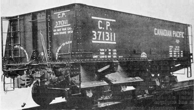 General Service Car, Canadian Pacific Railway (Little Otis as originally built). The accompanying illustration shows one of the 140 Hart-Otis general service cars built for the C.P.R. by Canadian Car & Foundry Co. at its Montreal plant, as announced previously in Canadian Railway and Marine World. The floor of the car is composed of 8 drop doors, 4 on each side, hinged to the center sill, and operated in pairs. The operating gear is the Hart-Otis Car Co.'s latest improved rolling shaft type, the operating shaft being 2 1/2 inches open hearth mild steel. The car floors have an apex 14 1/2 inch high along the center line by 2 feet 4 inches at the floor line, and are built up of steel plates and angles, entirely covering the center sills. Following are the chief dimensions: Length inside coupler knuckles ... 27 feet 3 1/2 inches Length over end sills ... 24 feet 4 1/2 inches Length inside ... 22 feet 5 inches Width overall ... 9 feet 11 1/4 inches Height inside ... 5 feet Height from rail ... 9 feet 4 13/16 inches Height from rail to floor ... 4 feet 4 13/16 inches Truck centers ... 13 feet Wheel base of truck ... 5 feet 6 inches Wheel base of car ... 18 feet 6 inches Doors on each side ... 4 Width of door opening ... 2 feet 2 inces Length of door opening, intermediate ... 5 feet 7 inches Length of door opening, end ... 4 feet Capacity ... 1,034 cubic feet Wheels ... 850 pounds  A Little Otis car with extended wooden sides - 1973 Photographer?  A Little Otis car with extended steel sides - Date? Photographer? - CSTM Collection.  The construction of the Canadian Pacific Railway in the 1880s is inextricably linked with the settlement and development of Western Canada. Glenbow Museum has an extensive collection of more than 6,000 railway-related historic photographs, which document the building and operation of the Canadian Pacific Railway as well as other railways in the West. The locomotives in these photographs, many of which can be identified by their numbers, were photographed in Alberta and British Columbia. The photographs show the engines on the prairies and in the Rocky Mountains, in roundhouses, at stations, with their crews, and plowing their way through immense amounts of snow. Click on any photo above to enlarge it.               
The Prince of Wales' Canadian Tour by Rail and Water  The Prince of Wales CPR train consisted of 2 steel baggage cars, tourist car "Chinook", 2 sleepers, "Carnarvon" and "Chester", diner "Canada", compartment car "Empire", private car "Cromarty" owned by director J.K.L. Ross, and Lord Shaughnessy's official car "Kilarney". The principal portion of the Canadian tour which the Prince of Wales is now making is over the Canadian Pacific Ry. and its British Columbia Coast, Lake, and River Steamship Lines, but parts of it will be over the following railways: Algoma Central & Hudson Bay, Canadian National, Esquimalt & Nanaimo, Grand Trunk, Grand Trunk Pacific, Kettle Valley, Timiskaming & Northern Ontario. The Prince's first railway experience in Canada was at Quebec on 22 Aug 1919 when, after motoring from the city to the north end of the Quebec Bridge, he was taken over it and back again on a special Canadian National Rys. train, to which were attached fitted up flat cars for observation purposes. Among those present were: Lieut.-Col. C.N. Monsarrat Chairman of the Bridge Commission, Ralph Modjeska one of the members of the commission, Phelps Johnson President, G.H. Duggan Chief Engineer, and G.F. Porter of the St. Lawrence Bridge Co., representing the builders. The special train, which will be used throughout the railway portion of the Prince's tour, has been provided by the C.P.R. In addition to the locomotive, which will be provided by the different lines over which the party travels, the all steel train consists of two baggage cars, tourist car "Chinook", sleeping car "Carnarvon", dining car "Canada", sleeping car "Chester", compartment car "Empire", private car "Cromarty", owned by J.K.L. Ross one of the C.P.R. directors, and Lord Shaughnessy's car "Killarney".  Dining Room Killarney. Several of the cars, notably the "Chinook", the compartment, tourist, and baggage cars, have been completed for the occasion, but are specially interesting as they are the first of a new series that have been adopted for the entire C.P.R. system, and are equipped with everything that is modern in railway car building. After this journey they will be drafted into regular service. The Prince of Wales will live on the train for about two months, making the "Killarney" his headquarters throughout the trip. The train is accordingly equipped with modem devices and conveniences, thus enabling the Prince and his suite to enjoy as nearly as possible the comforts of a stationary dwelling. Nothing has been overlooked from the handle set at the bedside to regulate the temperature of the stateroom, which is a standard appliance in C.P.R. equipment, to the telephone that brings the Prince in touch with all parts of the train. In order to distinguish it from all other cars on the line, the "Killarney" bears, the Prince's feathers and motto. The car is entered from the rear by an observation platform large enough to accommodate several arm chairs. The first compartment is also devoted to observation, a compact little room fitted with a lounge, easy chairs, a table, and electric fans. On rainy days or in cold weather the scenery may be viewed more pleasantly through the large windows on either side, than from the platform outside. A speed recorder adds interest to the journey and an air pressure gauge indicates the application of the brakes by the locomotive man. Next to the observation compartment is a section devoted to the Prince's secretary, after which is the bedroom to be occupied by the Prince. A rich simplicity characterizes this compartment, which is finished in white mahogany inlaid with a fine line of ebony outlining the panels. Built into the walls across the end is the bedstead, finished with little ornamentation in the white mahogany of the room. Over the bed may be pulled a roller curtain to protect the occupant from the dust and draughts of the ventilators in the ceiling. The door is a full length mirror and an oval glass is set above the dressing table. The fittings of the dressing table and toilet are brass in harmony with the woodwork and a large receptacle is screwed into the wall to hold a thermos bottle. Next to the Prince's bedroom is a second stateroom with two berths similar to that assigned to the secretary. Then in a niche in the wall is a shower bath of white tiles and porcelain.  Sitting and Observation room in Killarney. The central portion of the car is devoted to the dining room which is tastefully decorated in royal blue. Beneath the little extension table is a heavy blue pile carpet with six chairs upholstered in tapestry to match. The curtains and even the drawers of the sideboard carry out the color scheme, for the silver table service reposes between divisions of blue tapestry velvet. Between the sideboard and the window is a secretaire with pens and paper. Above it is a miniature bookcase. With steel walls finished in imitation mahogany, a kitchenette, pantry, icebox, service counter, charcoal heater, and chef's bedroom, have been fitted into limited space beyond the dining room. The compartment car "Empire" is reminiscent of an English coach, for the seats are partitioned off and joined only by the narrow corridor that runs down the length of the car. At each end is a commodious drawing doom, with a sofa, in addition to the upper and lower berths. The color scheme of this car is grey and green, the grey of the marbleized wall finish contrasting happily with the green of the heavy friezette plush upholstery. In each room is to be found an individual heating control. The members of the Prince's immediate suite occupy the "Killarney" and dine with him in the dining room laid for six. Six more are accommodated in the "Cromarty". The dining car is a pleasant place where tables for four and for two are placed at the windows down each side of the car. The rich brown tones of the Cuban mahogany walls and ceilings combined with the green hangings and accentuated with inlaid lines of satinwood harmonize beautifully. This car will accommodate 30 persons at a sitting. The sleeping cars present only one feature of exceptional interest to the travelling public well acquainted with the details of the C.P.R. sleeping cars. Tucked away in a corner is a dispensary as shipshape as the doctor's office on a ship. A special chair has been arranged for the patient, if such there be, and the showpiece of the little office is a patent light fixture with which the physician can examine the throat. In one of the baggage cars the dark closet and workroom of the official photographer have been arranged. There are shower baths and sleeping compartments in the baggage cars too, and cold storage cupboards were the chef keeps his supplies. An auxiliary generator is also installed here, to provide electric light throughout the train if it is stationary for any length of time. The locomotive, in addition to the regular signal flags, has two staffs each bearing the royal standard, with the Prince's insignia. From the royal standards in front of the locomotive, to the electric searchlight at the rear end of the car "Killarney", the train is 780 feet long, and its total weight without passengers is figured at about 1,000,000 pounds. The locomotive and 9 cars, with interior decorations and furnishings, are said to have cost over $750,000. E.W. Beatty, President of the C.P.R., is represented throughout the trip by A.B. Calder, Assistant General Passenger Agent, Montreal. The Canadian National Railways is to be represented, during the portion of the trip over its lines, by A.J. Hills, Assistant to the President, and the Grand Trunk Ry. is to be similarly represented by H.R. Charlton, General Advertising Agent. R.G. Chamberlin, Chief of Investigation Department C.P.R. Montreal, has been appointed by the Dominion Government as Commissioner of Police of Canada and as such is in charge of police arrangements during the Prince's entire Canadian tour.  Bedroom in Killarney. The schedule provided for the C.P.R. royal train is to leave Quebec, 24 Aug 1919 at 14:00, arrive at St. Martins Junction at 18:30, leave there at 20:00 and reach the Government House private siding at North Toronto, 25 Aug 1919 at 09:00. But the Prince decided to motor from Quebec to Three Rivers with some of his staff, arriving there at 18:25 and boarded the train which was waiting there for him, reaching Toronto, 25 Aug 1919, at 10:10. After spending three days in Toronto the Prince left again from the private siding, North Toronto, 27 Aug 1919 at 23:30, arriving at Ottawa Central Station on the morning of 28 Aug 1919. The itinerary for the balance of the trip is as follows, subject to alteration: Canadian Pacific Ry - 1 Sep 1919 Leave Ottawa Central Station 23:30, arrive North Bay 2 Sep 1919, 09:55. Timiskaming & Northern Ontario Ry. - 2 Sep 1919 Leave North Bay 10:30, arrive Cobalt 14:30, leave 17:30, arrive Timmins 22:00. 3 Sep 1919 Leave Timmins 13:45, arrive North Bay 22:20. Canadian Pacific Ry. - 3 Sep 1919 Leave North Bay 23:30, 4 Sep 1919 Arrive Sault Ste. Marie 10:00. Algoma Central & Hudson Bay Ry. - 4 Sep 1919 Leave Sault Ste. Marie 13:30, arrive Oba 22:00 Canadian National Ry. - 4 Sep 1919 Leave Oba 22:30, 5 Sep 1919 Arrive Orient Bay 07:00. There the Prince and party will leave the train to spend three days fishing the Nipigon River, and under canvas. The arrangements for this are being made by the Canadian National Rys., co-operating with McKirdy & Sons outfitters, etc. The train will be sent on from Orient Bay to Nipigon, and will leave there with the Prince and party 8 Sep 1919 at 11:50 reaching Port Arthur 15:15. Canadian Pacific Ry. - 8 Sep 1919 Leave Port Arthur 16:00, arrive Fort William 16:15, eastern time. Leave 19:00 central time. 9 Sep 1919 Arrive Winnipeg 11:00. 10 Sep 1919 Leave Winnipeg 19:00. 11 Sep 1919 Arrive Saskatoon 11:00, Leave 18:00. 12 Sep 1919 Arrive Edmonton 10:00. 13 Sep 1919 Leave Edmonton 00:30, Arrive Calgary 08:30. 15 Sep 1919 Leave Calgary 15:45, Arrive High River 17:00. 16 Sep 1919 Leave High River 19:50, Arrive Calgary 21:00. 17 Sep 1919 Leave Calgary 06:15 or earlier. Arrive Banff 10:00, Leave 18:00, Arrive Lake Louise 19:20. The party will spend the night at Chateau Lake Louise, 3 1/2 miles from the station. 18 Sep 1919 Leave Lake Louise 12:00, arrive Field 13:50. The Prince will go independently at Field, and will visit Yoho Valley, Takakaw Falls, and Emerald Lake. 20 Sep 1919 Leave Field 08:00, Arrive Revelstoke 13:50, Leave 17:30, Arrive Sicamous 20:00. 21 Sep 1919 Leave Sicamous 14:00, Arrive Kamloops 17:10, Leave 18:10. 22 Sep 1919 Arrive Vancouver, 10:00. 23 Sep 1919 Leave Vancouver by C.P.R. S.S. Princess Alice, 13:30, Arrive Victoria 18:15. Esquimalt & Nanaimo Ry. - Leave Victoria and arrive Qualicum at times to be arranged. Short stops will be made at Duncans, Ladysmith, and Nanaimo. The Prince will leave for an island trip, independent of the train, returning to Victoria 28 Sep 1919. Canadian Pacific Ry. - 28 Sep 1919 Leave Victoria by C.P.R. S.S. Princess Alice 23:59, midnight. 29 Sep 1919 Arrive Vancouver, 07:30. The Prince will proceed to New Westminster by motor car and open the exhibition. The train will be sent to New Westminster to meet him. C.P.R. and Kettle Valley Ry. - 29 Sep 1919 Leave New Westminster 13:30. 30 Sep 1919 Arrive Penticton 01:00. The route from Hope to Penticton is via the Kettle Valley Ry., through the Hope Mountains. From Penticton a steamboat and motor trip will be made, visiting Kelowna and Vernon. The C.P.R. Sicamous will be used on Okanagan Lake. 30 Sep 1919 Leave Penticton 18:30. 1 Oct 1919 Arrive Nelson, 10:00. The train will be sent by car ferry and rail from Nelson to Kootenay Landing and the party will leave Nelson by C.P.R. steamboat Nasookin for Kootenay Landing, calling at Balfour enroute and arriving, at Kootenay Landing at 08:30. Canadian Pacific Ry. 1 Oct 1919 Leave Kootenay Landing 21:00. 2 Oct 1919 Arrive Macleod 10:00, Leave 10:30, Arrive Lethbridge 13:00, leave 17:00. 3 Oct 1919 Arrive Medicine Hat 09:00, Leave 10:30, arrive Maple Creek 13:30, Leave 14:00, Arrive Swift Current 17:00, Leave 17:30. 4 Oct 1919 Arrive Moose Jaw 10:00, Leave 12:30, Arrive Regina 14:30. Train to be placed on Grand Trunk Pacific Ry. siding near Government House. Grand Trunk Pacific Ry. - 6 Oct 1919 Leave Regina 15:00, Arrive Edenwald 16:30, where there will be a three days' duel shooting expedition. 9 Oct 1919 Leave Edenwald at time to be arranged, arrive Qu'Appelle 23:50. Canadian Pacific Ry. - 10 Oct 1919 Leave Qu'Appelle 01:00, Arrive Brandon 10:00, Leave noon, Arrive Portage La Prairie 14:00, Leave 14:30, Arrive Winnipeg 16:30. 11 Oct 1919 Leave Winnipeg 02:00, Arrive Fort William 14:30 central time, Leave 15:50 eastern time. 12 Oct 1919 Arrive Biscotasing 10:00. A stop of 4 days will be made at Biscotasing to visit Northern Ontario woods, lakes, and rivers. 17 Oct 1919 Leave Biscotasing 21:00. 18 Oct 1919 Arrive West Toronto 08:25, Arrive Hamilton 10:00. Grand Trunk Ry. - 18 Oct 1919 Leave Hamilton 21:30, Arrive Niagara Falls 22:30. 20 Oct 1919 Leave Niagara Falls noon, Arrive Brantford 14:30, Leave 18:00. 21 Oct 1919 Arrive Guelph 10:00, Leave 15:00, Arrive Stratford 17:00, Leave 18:00. 22 Oct 1919 Arrive Woodstock 11:00, Leave noon, Arrive Chatham 14:00, Leave 15:00, Arrive London 15:00, Arrive Windsor 18:30, Arrive London 16:30. 23 Oct 1919 Leave. Canadian Pacific Ry. - 24 Oct 1919 Leave Windsor noon, Arrive London 15:20, Arrive North Toronto 20:20. Grand Trunk Ry. 25 Oct 1919 Leave Toronto at time to be arranged, arrive Kingston at 10:00. 27 Oct 1919 Leave Kingston, Arrive and Leave Brockville, Arrive Vaudreuil, at times to be arranged. Canadian Pacific Ry. 27 Oct 1919 Leave Vaudreuil at time to be arranged, arrive at Windsor St. Station, Montreal, 12:30. 31 Oct 1919 Leave Windsor St. Station, Montreal 13:30, Arrive and Leave St. Armes, and Arrive Ottawa, at times to be arranged.  Private Car used by the Prince of Wales, afterwards King Edward VII, during his Canadian Tour in 1860.
Trans-Canada Trains 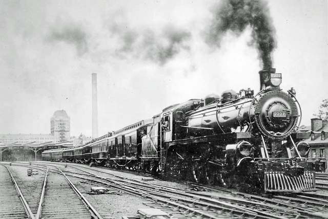 Trans-Canada Limited train, Canadian Pacific Railway, leaving Windsor Street Station, Montreal, 1 Jun 1919, on its first run to Vancouver, B.C., 2,885.8 miles. As announced in advance, in Canadian Railway and Marine World for June, the C.P.R.'s new Trans-Canada Limited started running on June 1, the first westbound train leaving Montreal at 15:30 and reaching Vancouver, Jan 6, at 10:00, (likely an error ) making the annual running time for the 2,885.8 miles, 93 1/2 hours. It was never behind time on the whole run, and at some points exceeding its schedule, and it could have reached Vancouver considerably earlier. As stated above, the running time from Montreal to Vancouver is 93 1/2 hours. From Toronto to Vancouver it is 89 3/4 hours. Eastbound the running time is, from Vancouver to Montreal, 92 1/4 hours, and from Vancouver to Toronto, 88 hours. On leaving Montreal the train had about 100 passengers and picked up others enroute. The highest number of passengers was 125. The passengers on the cross country flight were largely from Boston, New York, Washington, D.C., and San Francisco. Some left at Banff, but the majority went through. Following are particulars of the equipment of the Trans-Canada Limited trains. Train 7, from Montreal to Vancouver, and Train 9, from Toronto to Sudbury, where it is consolidated with train 7: 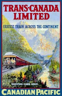 Dining car, Montreal to Vancouver, Toronto to Sudbury; Train 8, from Vancouver to Montreal, and train 10, from Sudbury to Toronto: Dining car, Vancouver to Montreal, Sudbury to Toronto; The new trains, east and west, require for their operation, 59 sleeping cars, the value of which at present prices is approximately $2,478,000, fifteen dining cars $750,000, twelve observation cars $480,000, five compartment cars $210,000, twelve baggage cars $180,000, and 24 locomotives $1,464,000, making a total of $5,762,000 on a very conservative estimate. The labour cost is less easy to compute, but each train itself requires 12 train crews, and 24 locomotive crews. The first westbound train carried many photographers, who took views enroute.
Canadian Pacific Railway Locomotive Tenders The C.P.R.'s standard locomotive tender, which for several years has been remarkable for a number of original ideas incorporated in its design, has recently undergone a number of modifications designed to promote both its utility and the safety of the engine and train crews working in connection therewith. As formerly constructed, the tender had a slope sheet at the usual angle which necessitated the use of a supplementary hinged sheet covering the upper half and arranged so as to permit of its being lifted by means of an air cylinder inside the water compartment when it was desired to throw the coal from the back part of the coal space forward to the shovel sheet. This form of coal passer has likewise been a standard feature of C.P.R. tenders for a number of years.  Canadian Pacific Railway Locomotive Tender. Plan and longitudinal section. Without other modification to the tank portion of the tender, a new form of coal container has been applied, same having slope and bottom sheets independent of the tank with the former placed at an angle about 30 degrees steeper than formerly, the result being that coal automatically delivers itself at the shovel sheet and the coal passing arrangement has been dispensed with. This, of course, serves to diminish somewhat, the coal carrying capacity of the tender, but the advantages gained through the elimination of the coal passer and the fact that quantities of fuel no longer remain inert in the coal space for indefinite periods of time are felt to be a full compensation for this seeming disadvantage.  Canadian Pacific Railway Locomotive Tender. Cross sections. The tanks of C.P.R. tenders are constructed with the idea of making them carry their own load without the assistance of a heavily constructed underframe. This is accomplished by dividing the water space longitudinally on the center line, and transversely over the bolsters, as well as at intermediate points, where it was originally desired to support the load of coal on the slope sheet, with plate diaphragms. These not only make of the tank a self supporting structure, but serve at the same time to reduce the surging of the contents and make the tender ride more smoothly. Either side of the rear bolster diaphragm are large triangular gusset plates tending to supplement the transverse diaphragms in their function of stiffening the structure. The corners of the diaphragms are cut off to simplify attachment and to permit of equalization of the contents in the several compartments of the tank, in addition to which there is a series of 12 by 18 inch oval openings 18 inches above the bottom, which, in addition to serving the above purpose, also facilitate interior inspection, cleaning, and repairs. The well of the tank is placed just back of the rear bolster diaphragm and underneath the well the longitudinal diaphragm is so cut and perforated as to serve the purpose of a ladder for entering the tank. This form of tank structure requires the minimum in the way of underframe construction, the latter consisting merely of a pair of 13 inch channels terminating in draft housings at either end and fitted with the necessary castings in the form of centerplates, bolster arms, and filling pieces. The tender is designed for application to locomotives having the vestibuled cab, a further standard feature of C.P.R. locomotive equipment. The coal gate is but 32 1/2 x 24 inches in size, being cut into the otherwise solid plate front end of the coal hopper and is closed by means of a vertically operating steel plate slide. Through this relatively small gate, access to practically all portions of the shovel sheet is possible from the fireman's position of the firing deck. This design of tender has been strongly commended because of the safety features incorporated in its construction. Prominent among these is the arrangement of the coal bunker, whereby it is not necessary for trainmen to climb over the coal pile in getting to the rear of the tender. This is accomplished by bringing in the top of the bunker a distance of 15 inches on either side, forming a runway of that width. A hand rail affords security to those having occasion to pass from front to rear or vice versa by this route. Vertical hand rails are provided at the rear corners immediately above corner steps, a further safety measure which is of especial value in switching. The frame extends beyond the end of the tank a sufficient distance to afford a platform on which to stand, there being a corrugated step plate near either end and a longitudinal hand rail across the back end of the tank at suitable height. Access to the top of the tank from the rear platform is had by means of a ladder placed near the left-hand corner for that purpose and around the top of the tank at the rear, is still another hand rail for the safety of men having to climb over the back of the tender. - Railway Review. 
Turbo Chargers In the diesel shop they were changing a Turbo on the 5915, a GMD SD40-2. They had the old turbo out on the floor, so I took a few shots of the offending apparatus plus some of the behind-the-scenes gear works.  Canadian Pacific SD40-2 number 5915 in the diesel shop - 14 Jun 2014 Andy Cassidy. Figures 1 and 2 show the overall view of the back side of the Turbo at the drive end. The Turbo Lifter is attached to the top of the stack, and the Turbo is sitting on a special holder on the floor. To the uninitiated, one may wonder why a turbo has a bunch of gears attached. To be brief, the GM (General Motors) 2 cycle engine will not run in naturally aspirated conditions since they have no intake stroke like a 4 cycle Alco (American Locomotive Company) or GE (General Electric). As such the Turbo needs to be mechanically driven by the engine gear train to spin it and provide combustion air to the cylinders at starting and in low speed situations. In notch 7 and 8 throttle positions the engine exhaust is sufficient in heat and volume to spin the turbo above the mechanical drive speed. An internal overriding clutch mechanism allows the mechanical drive to be disengaged at that point. In figure 2, the clutch mechanism is internal and behind that brass colored ring which is part of the drive gear (Figure 2), and driven by the exposed idler gear just to the lower left. The idler gear is driven by the Spring Drive Gear Assembly, as seen in Figures 3 and 4, and the Stub Shaft of that drive sits in the opening at the bottom of the Turbo, Figures 1 and 2. Whew! Pause and re-read, there might be a test.  Figure 1 - Turbo drive end - 14 Jun 2014 Andy Cassidy.  Figure 2 - Turbo drive end close-up - 14 Jun 2014 Andy Cassidy. Above the gear train housing is the Exhaust Manifold Inlet to the Turbo. The exhaust manifold segments run the length of the engine in the top of the "Vee" between the cylinders and attach to a screen that filters out any damaging debris from entering the turbo should some internal engine part come through the exhaust. Like a broken valve, or hunk of piston, etc. Turbos are VERY expensive to repair or replace. So the screen can be worth its weight in gold when engine damage results in solids coming through the exhaust system.  Figure 3 - Camshaft Drive Gears and Spring Drive Gear Assembly - 14 Jun 2014 Andy Cassidy.  Figure 4 - Close-up of the Spring Drive Gear Assembly - 14 Jun 2014 Andy Cassidy. The exhaust is directed internally past the Turbine Wheel, then out the stack that the lifter is attached to. The spinning of the turbine also turns the Inlet Air Impeller on a common shaft. The impeller, seen in Figures 5 and 6, pulls air in like a vacuum cleaner and forces it out the two Scrolls. The Scroll exiting on the near side feeds the right bank cylinders, and the Scroll on the left (Figure 6 - face down on the stand), feeds the left bank cylinders of the engine. (There are Aftercoolers between the Scrolls and the Air Boxes to cool the compressed inlet air. (Not seen here).  Figure 5 - Inlet Air Impeller - 14 Jun 2014 Andy Cassidy.  Figure 6 - Turbo assembly with Scrolls resting on a floor stand - 14 Jun 2014 Andy Cassidy. Figures 3 and 4 show the engine side of the works. As noted, in Figure 3 you can see the Exhaust Manifold Screen Assembly that attaches directly to the turbo up top. The two big gears with counterweights are the Camshaft Drive Gears. One overhead cam on each cylinder bank. Below and between is the Spring Drive Gear Assembly. This assembly is driven off the crankshaft and in turn spins the camshaft gears with the back gear. The front gear on the pack drives the Turbo Idler Gear, and the reason for the springs (Figure 4) is to dampen vibration or shock to the turbo. In Figure 3 you will also notice a shaft assembly sticking out at the top left. This is the drive for the Auxiliary Generator, plus the Main Alternator and Traction Motor Cooling Fans. This is driven by an Auxiliary Drive Gear Assembly that's attached to the turbo housing once installed, and is not shown in any of the photos. A GE Turbo is simple compared to a GM as there is no external mechanical drive. This is why Alco's, and to some degree GE's, produce black smoke under acceleration. Turbo lag starves the engine of air till it gets up to speed. On the GM's the turbo is more like a Supercharger than a Turbo since it spins up to speed right along with the engine due to the mechanical drive. The overriding clutch mechanism inside the GM Turbo is generally a cause for replacement. Over time they wear out and result in the clutch dropping out at low speed before the exhaust is capable of taking over the task of driving the Turbo. Thus the engine will labour, gasping for air. In the mean time the governor is going Full Rack pouring the fuel to an engine that is not responding to the extra fuel. Smoke abounds! Then, as the engine struggles and slows down, down, down, the clutch will re-engage. Suddenly the engine roars to life full speed ahead with great gusto and clouds of smoke as it clears its throat. Sometimes the Overspeed will trip as a result and kill the engine. It's quite the spectacle to watch and hear. Scares people if they don't know what's going on. My recent post on the Turbo change in CP 5915 (GMD SD40-2), stirred up a few comments. So I thought it worthy of note to go a touch further on a couple of different fronts.  Canadian Pacific General Electric AC4400CW number 9838 in the diesel shop - 9 Aug 2006 Andy Cassidy. First, to expand on the operation of the General Motors (GM) 2 cycle locomotive engine, it was pointed out to me I should have touched on the fact that not all GM engines have a Turbo. I never gave it a thought at the time, but yes the GM engines in the lower horsepower ranges get their breathing air from mechanically driven Roots Blowers. I thought I had some Roots Blower internal workings photos on file, but not the case. These blowers are very reliable devices and virtually never need replacing for the most part, so one doesn't see them on the shop floor that often. In any event some years ago we had a flat car in the yard with two GM engines on board that give a good view of the external workings. The first two shots are of a 12 cylinder roots blown engine.  Figure 7 - GM 12 cylinder roots blown engine - 9 Aug 2006 Andy Cassidy.  Figure 8 - GM 12 cylinder roots blown engine - 9 Aug 2006 Andy Cassidy. One can see the two Roots Blowers mounted at the back of the engine on top of the Air Ducts that feed the air to the Air Box along the length of the engine (top hand hole covers). Above the blowers are the Air Filter Holders, minus the filter media. The Roots Blowers don't need Aftercoolers like the Turbo equipped engines as they don't generate the heat a Turbo does compressing air. You'll note there are no Exhaust Manifolds on the top of the engine, as they're not involved in the air intake system. Now as a comparison, the other engine (part of a Gen Set) on the flat car was a 20 cylinder Turbo charged engine.  Figure 9 - GM 20 cylinder turbo charged engine - 9 Aug 2006 Andy Cassidy. As you can see, the Exhaust Manifolds are attached together and direct the exhaust past the screen and into the Turbo at the back of the engine. The Stack outlet is covered with a tarp to keep the rain out. The big box above the generator is for the air filters at the inlet to the Turbo. And finally, the Turbo Outlet Air is directed through an Aftercooler on each side before being fed to the Air Box. The Aftercooler has that blue water pipe attached to it, and the water from the cooling system provides the cooling. Basically it's a small radiator. Finally, back in 2013 they were changing out the Turbo on CP 9838 (GE AC4400CW). As noted in the previous message, GE's employ 4 cycle engines that don't need any mechanical drive from the engine other than the exhaust. As such they are a pretty easy repair but still expensive though. Shown here in the final photos are shots of the removed Turbo from this units 7FDL engine.  Figure 10 - GE Turbo Exhaust Inlet - 9 Aug 2006 Andy Cassidy.  Figure 11 - GE Turbo Exhaust Inlet - 9 Aug 2006 Andy Cassidy. In the these shots it rests on the shop floor, and you are looking at the Exhaust Inlet side of the unit. The outlet is at the top with the lifter attached. The third shot is about a month later and the same Turbo is sitting outside the Stores Department waiting to be shipped out. In this view you are looking at the Air Inlet side and the two Outlet Scrolls that feed each cylinder bank. The overall size is about the same as the GM Turbo, but without the gear train, and all the nut and bolt connections.  Figure 12 - GE Turbo Air Inlet and two outlet Scrolls - 9 Aug 2006 Andy Cassidy. The next photo shows the Exhaust Stack/Spark Arrestor that sits atop the Turbo when applied to the engine. This is the part you see sticking out of the roof on these locomotives. The newer GE EVO engines have a similar Turbo, just a bit more compact and with different Scroll Outlets.  Figure 13 - GE Turbo Air Inlet and two outlet Scrolls - 9 Aug 2006 Andy Cassidy. That's it for mechanical lessons for now.
The Canadian Pacific Railway's Windsor Street Station, Montreal 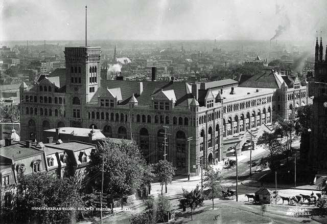 Windsor station Montreal before - Date? Photographer? The extensive additions to the Windsor Street station, Montreal, are rapidly approaching completion. A full description, with plan, of the trackage and approaches appeared in Canadian Railway and Marine World for November.  Windsor station Montreal after - Date? Photographer? In the summer of 1910 the foundations were laid of an addition to the old building, to extend the frontage along Windsor street to a total of over 490 feet with a frontage on St. Antoine street of over 170 feet. There were two problems to be faced, one architectural, the other engineering. The architect's difficulty was to devise a facade which would look harmonious and impressive from every point of view, in spite of the fact that there was a difference in elevation on Windsor Street of 40 feet between St. Antoine and Osborne streets. The engineering problem was to find a satisfactory foundation on rather treacherous soil for the massive tower, which the architect proposed. The sinking of the foundations delayed the work considerably at the initial stages, but eventually a satisfactory base was found, and the building began to rise with a structural steel frame, all the columns of which rest upon heavy concrete foundations carried to rock by means of cylindrical caissons. The variation in levels had one satisfactory result, namely, that room was found for vast vaults beneath the main floor of the building and beneath the tracks, in which there is storage capacity sufficient to accommodate records for many years to come. These vaults cover a ground area of 66,000 square feet, still leaving room for an immigration hall covering 10,000 square feet, Chinese waiting room, covering 6,900 square feet, and third class passenger waiting room, covering 3,000 square feet. The cubic capacity of the new portion of the building, exclusive of vaults under tracks, but including the splendid concourse, is 4,703,000 cubuc feet, while the viaducts total another 1,000,000 cubic feet, and the power houses an additional 220,500 feet. The tower is 15 stories high, or 16 including the basement, and its top is 225 feet above the level of St. Antoine St. It contains water tanks, with a combined capacity of 30,000 gallons, and is said to be the most massive tower in Canada. The general waiting room, in the main building, has a ground area of 7,800 feet.  The general waiting room - Date? Photographer? The new addition alone contains 2,800 tons of steel, apart from the steel used in the train sheds. The building when completed will have 13 elevators, 8 for passengers (2 of which have a lifting capacity each of 7,000 pounds.), 4 for freight and baggage, and 1 for the kitchen and restaurant. In the construction of the exterior of the building limestone from quarries in the Province of Quebec was used, and the labour employed was almost entirely native. The steel was manufactured at Lachine by the Dominion Bridge Company. As many as 600 men were employed at one time on construction, the rivetters and erectors being chiefly recruited from the Indian reservation at Caughnawaga. The stonemasons were French Canadians. The interior fittings were very fine, marble being used exclusively in the principal halls and corridors. Italy, France, Indiana, and Tennessee have each contributed from their quarries, some of the stone coming from Euville, and some of the marble from the Botticino quarries. The train sheds have been planned to cover all the tracks, which have been increased to 11 in number. On 6 tracks the sheds are 1,000 feet long, on 2 tracks 800 feet, on 2 more 550 feet, and on track 1, intended particularly for suburban traffic, 420 feet. Over 2,000 tons of steel have been used in these sheds, exclusive of the concourse. The area covered is 205,000 square feet, or about 5 acres. The train sheds are of the Bush pattern, and special care has been taken to provide roof drainage and to ensure dry and clean platforms at all times. The skylights are designed so as to be always clear, and snow can be shovelled through slots in the roof onto cars below. A copper hood over every skylight is specially designed to allow of ventilation and yet to prevent snow or rain from drifting in. There is a system of fire protection in case of cars taking fire in the station, pipes being laid with plentiful supply of water under high pressure.  Windsor station train shed - Date? Photographer? 
Canadian Pacific Railway Telegrapher's Typewriter Now before I begin, I must tell you that I have been searching for over 25 years for what in my experience is the most elusive Canadian railway artifact ever, a lowly Canadian Pacific Railway telegrapher's typewriter. Now you may say to yourself, "that shouldn't be so hard to find, every station had one, there must be thousands of them out there!" and you would be absolutely right, every station had one, and at one point there were thousands out there. But not today. In 25 years of active search across Canada I have seen exactly one come up for sale. I passed on it at the time and have kicked myself ever since.  A Canadian Pacific Railway Telegrapher's Underwood Typewriter - Date? Thom Cholowski - Thom Cholowski Collection. So why are they so rare? Allow me to explain. For the simple reason because it is totally useless to anyone who is not a telegrapher. Telegraph typewriters (known as mills) are specifically made to write messages sent over the wireless or telegraph lines. It types only in CAPITAL letters (to prevent confusion) and there is no shift key. The keyboard is laid out differently than a normal typewriter keyboard (due to the fact that the numbers 1 and 0 have their own key). It has less characters than a normal typewriter. In short, it has no practical use as a typewriter outside of a communications center that uses telegraphy so no one bothered to "liberate" one for home use once they were struck off record. Well, this weekend I decided to take a trip to Regina to see the sights. I stopped into an antique mall and among the chattle I found not one but two telegraph mills. The first one was a 1942 Underwood model 5, originally issued to the Royal Canadian Navy. It had several unique features such as a vibration dampening mechanism and corrosion resistant parts (useful on a ship at sea) as well as a number 1 key and a struck out number 0 in addition to typing only in all capitals.  A closer look at the keyboard - Date? Thom Cholowski - Thom Cholowski Collection. The second one is the incredibly elusive Canadian Pacific Railway typewriter I've been searching for. It is an Underwood number 6, dated 1934. It has no shift key, has a "speed tab" bar on the right hand of the keyboard frame, types only in capitals, and has a Canadian Pacific Railway inventory number stamped on the side of the frame. There are other significant details to set it apart from a normal typewriter, but I'll spare you the technical details. Sufficed to say, it is unequivocally a Canadian Pacific Railway telegrapher's mill.  The speed tab bar - Date? Thom Cholowski - Thom Cholowski Collection. So there you go. It just goes to show, perseverance pays off and you never know what's going to come your way! Thom Cholowski. 
Calgary Alberta - I caught one of the two new CP Multi Purpose Maintenance (MPM) consists backing into Ogden Yard on the morning of 30 May 2018.  Left front - 30 May 2018 Cor van Steenis.  Left rear - 30 May 2018 Cor van Steenis.  Left rear closeup - 30 May 2018 Cor van Steenis.  Nelson Station By Phil MasonBritish Columbia 16 April 2018  Because of the amount of structural damage caused by subsidence over many years, this has been a long and expensive procedure. Perhaps more than any other CP location, this is a place where friends from Montreal have spent and often started their railroad careers. Most worked as operators at various locations on the CP Kootenay Division based in this building. Stan Smaill, Grant Will, and both John and Andrew Sutherland all worked the Kootenay Division in the late 1960's and 1970's. Grant Will worked as a trainman out of Nelson, and I spent the fall of 1975 working there while laid off at Revelstoke.  Right hand rear of station - Apr 2018 Kylie Mason. The origins of this building were as a Columbia & Western station dating back to the 1890's, however it was expanded twice during the CP years. Because the different parts of the building settled down differently on its foundation (or lack thereof), throughout many years, the building was out of true and the bridge and building department made modifications compensating for that. That said, the building was very clean and well maintained in the 1970's, however the stairs to the upper floors and the upstairs floor itself had a definite slant to them. In the 1970's, this building was fully occupied with divisional offices, Rail Traffic Control (RTC) centre and a yard office. The foundation visible in the foreground on the first image was for a modern single storey extension which originally housed a cafe but later housed the telex machines and card sorters, etcetera, used by the yard office. In the seventies, at least part of it was a staff lunch room which contained parts of the earlier cafe. The Kootenay Division administered all the CP trackage from Midway in the west where it connected with the Kettle Valley Division, and all the way east to Crowsnest, British Columbia, where it connected with the Alberta South Division. Because of the coal, ore, and lumber traffic which originated on lines controlled from Nelson. In its heyday the Kootenay Division was one of the most profitable divisions for CP. Behind the station was an equally large freight shed which exists in a modified form as a hardware warehouse. During the 1980's and 1990's, the various offices housed in the building by CP moved elsewhere, mostly to Revelstoke. I think the RTC office was first to go, or perhaps the general office. By the early 1990's, the remaining staff moved to some trailers just west of the station, and the building was vacated. All along there was a desire to preserve the building, but CP pointed out that the building has structural issues and would be an extensive and expensive restoration. In time, the City of Nelson found the funds to do so, and these photo show the current state of the building. When I first encountered this building, it was in a paint scheme unique to the CP Kootenay Division, light green and yellow (Fernie and Erickson were the same colour), however in the summer of 1975, it was painted black and white, which it retained until restoration. I don't know if the current paint scheme relates to an earlier CP paint scheme. So far, the only tenant appears to be a tourist information office. Next door is a long preserved superintendents house. In the 1970's, the mailing address for this building was "CPR Nelson BC station, at the foot of Baker Street". Much of the other CP facilities at Nelson are gone, such as the diesel shop, the roundhouse, and most of the tracks. Freight trains to Yahk, Trail, and Castlegar still operate on a daily basis as part of CP's internal shortline the "Kootenay Valley Railway". It is interesting to see cars parked beside the station. In CP days, those spaces were reserved for managers and rigorously patrolled by the CP cop. Employee parking was some distance away. Phil Mason  Front trackside view of Nelson station - Apr 2018 Kylie Mason.  Front trackside view of Nelson station - 2008 Phil Mason. |