
Different Locations on the Canadian Pacific
The Canadian Pacific has in service on the Eastern Lines a number of electric train staff installations on short sections of single track, over which a large number of train movements are made. In addition to these, several installations have been made recently on portions of the Lake Superior division. It is the intention to double track the entire division, and the double track not being entirely completed, the staff system was installed on the remaining single track portions in order to eliminate train orders.
There are now in operation a total of twenty-one staff blocks, comprising in all forty-six staff instruments. No attempt has yet been made to operate an entire division with this system, the installations now in service being installed to take care of local conditions.

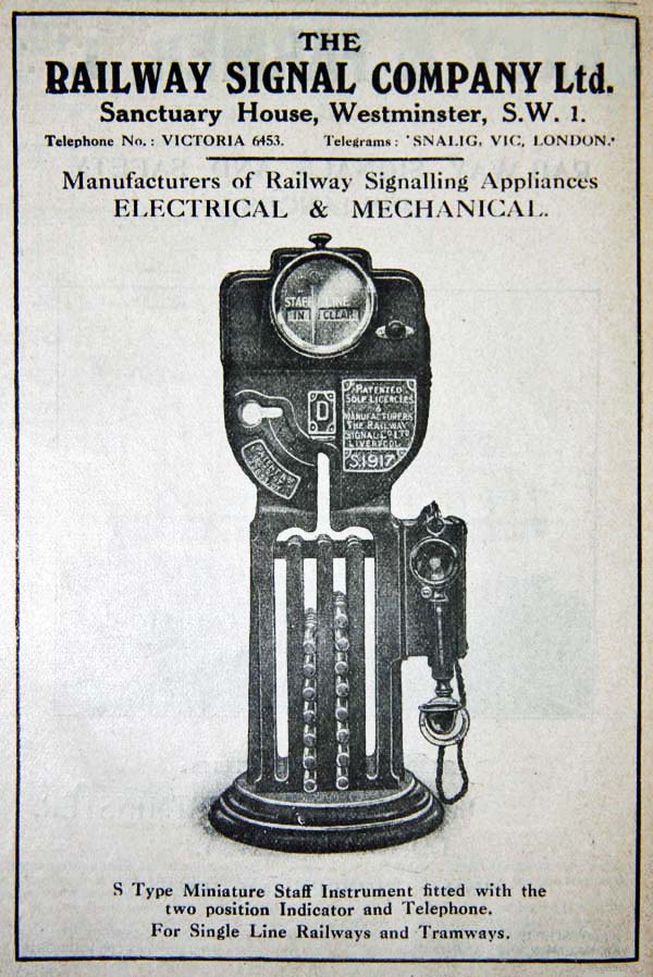
The instruments used are manufactured by the Railway Signal Company, of Liverpool, England, and are known as their type S miniature instruments, as shown, and were supplied by Messrs. Saxby & Farmer, Ltd., Montreal. The instruments are operated over a metallic circuit, consisting of two 210 pound B.&S. bare copper wires strung on the telegraph poles. Current for the operation of the staff instruments is furnished by a magneto generator. The chief advantage of magneto over battery working is that it is impossible to reverse the polarity, as has been done with battery working by a careless maintainer connecting cells wrongly, when recharging.
 The armature of the magneto can be rotated in one direction only, the handle of the magneto being provided with a ratchet and the driving gear with a special lock. Each magneto is equipped with two tapper keys so that one magneto serves current for block on each side of station. The keys are mechanically interlocked to prevent current from being sent in both directions at the same time.
Each staff instrument is equipped with an indicator which shows whether the instruments are "free" or "blocked", the indicator on both instruments reading "staff out, line blocked" when a staff has been withdrawn from either instrument, and "staff in, line clear" when no staff is out.
The staffs are steel rods, nine inches long, on which four brass rings are mounted. The staff marked A, Fig. 1, shows the appearance of this type, but the ordinary staff is indivisible. On one end a brass handle is mounted, on which is engraved the type of instruments to which a staff belongs, there being four types, and these are designated A, B, C and D. An "A" staff cannot be inserted in a "B" instrument, etc., making it impossible for the staff belonging to one block to be inserted in the instrument of an adjoining block.
Also, when two or more blocks adjoin one another, a brass plate on which is engraved the names of the stations at each end of the block, is riveted to the handle, in order to identify the staff with the particular block it governs. These name plates may be removed and new ones substituted should a pair of instruments be moved to another location.
Permissive movements through a staff block are made by staffs which are divisible into two parts (Fig. 1). The two parts of the staff must be tightly screwed together before the staff can be replaced in the instrument.
Each set of instruments is provided with forty staffs, twenty of these being divisible when the permissive feature is used. At one or two points where traffic is not heavy, and where train movements are nearly equal in both directions, only thirty staffs are provided. The capacity of each staff instrument is forty staffs.
Each staff instrument is provided with a telephone, which is worked over the staff line wires, providing a means of communication between operators, which is found of great convenience.
The method of operating the instruments is clearly shown in the instructions which are posted at each staff station, a re-production of which is shown herewith.
On staff sections over which there are few train movements at night, the operator has been dispensed with at the office at one end of the block by the installation of an "automatic operator" attachment. This attachment makes it necessary to use a battery instead of a magneto generator. The automatic operator consists of a stick relay, the armature of which is balanced, and on which there is one normally closed, and one normally open contact, the other members of these contacts being on pivoted weights. There is also a key for giving bell signals to the station at the opposite end of the block.
The wiring for a staff section, equipped with one automatic operation, is shown in Fig. 3. It is possible to operate a staff block without an operator at either station, by using this attachment at each end. Twenty No. 8 dry cells are used to furnish current for the operation of each automatic operator. When current is passed through the line, the armature is rotated in a direction to cause it to lift the weight on which the normally closed contact is fixed. When current through the line is broken, this weight causes the armature to rotate in the opposite direction a sufficient distance to close the other contact and cut-in a local battery. Current from this battery passes through a pair of coils holding the armature in this position, and releases the staff at opposite end of the block. When circuit is again broken, armature resumes its normal position by gravity, and the battery is then cut off the line.
Maniwaki Junction, it was necessary to install an auxiliary pair of instruments between Hull and Maniwaki Junction, Fig. 4. These four instruments are the same type, so that a staff from one instrument may be deposited in any other instrument, and a train obtaining a staff for this block, may move from... (text missing in original document) This attachment has now been installed on four staff sections on the Ontario division and is operating satisfactorily. One has also been installed on the Eastern division near Ottawa, in connection with an auxiliary staff block which is shown in Fig. 4.
In the staff block between Hull and Sparks Street Station, Ottawa, on account of a branch line joining this section at Hull to Sparks Street, Hull to Maniwaki Junction, or Maniwaki Junction to Sparks Street, or vice versa. When there is no staff out of the instruments, one or the other of the two pairs are out of phase, and a staff can only be obtained from the pair which is in phase. For instance, if a train is required to move from Hull to Maniwaki Junction, and the pair of instruments between Hull and Sparks Street are in phase, and the other pair out of phase, a staff must be withdrawn from the Hull Sparks Street pair at Hull, thus causing both pairs of instruments to be out of phase. Upon arrival of the train at Maniwaki Junction, the staff will be deposited in the instrument there causing the Hull Maniwaki Junction pair to be in phase. Should a train now be required to move from Sparks Street to Hull, it will be necessary for Hull to withdraw a Staff from the Hull-Maniwaki Set, and deposit in the Hull-Sparks Street Set. This will allow Sparks Street to withdraw a staff.
On account of Maniwaki Junction being a day office only, and to avoid the possibility at night of Hull depositing a staff in Hull-Maniwaki Junction instrument by mistake, and thus making it impossible to withdraw a staff from either pair, on account of Maniwaki Junction being closed, an automatic operator was installed at Maniwaki Junction, which enables Hull to withdraw a staff from that pair, without any action being taken by Maniwaki Junction.
It will be seen from the arrangement of instruments in Fig. 4 that this scheme may be carried out with as many auxiliary pairs as desired by arranging the wiring of the instruments so that only one pair will he in phase when no staff is out. Fig. 5 shows an installation of this character, having two auxiliary pairs instead of one, and with an automatic operator at each Junction point. This installation is now under consideration, and will govern movements of C.P.R. trains between N.Y.&O. Junction and Grand Trunk Junction, New York & Ottawa trains between N.Y.&O. Junction and the point where these trains leave the C.P.R. line, and C.P.R. locomotives between Grand Trunk Junction and the roundhouse.
No operator will be required at N.Y.&O. switch location, or at the C.P.R. roundhouse. Although the staff block will govern only to or from Grand Trunk Junction, staffs will be carried to Sparks Street station where instrument will be placed. As magneto generators are only equipped with two keys, capable of operating two pairs of instruments, a special switch will be provided at N.Y.&O. Junction to enable one magneto to be used to operate any one of the three sets of instruments.
Between McAdam Junction, New Brunswick, and Vanceboro, Maine, Atlantic Division, a staff block has been installed, with an unattended passing track attachment to allow trains to pass at Burpee, Fig. 6. Through movements between McAdam Junction and Vanceboro are made in the regular manner.

When it is desired to pass two trains at Burpee, special staffs are used. At McAdam, which is designated as the "initial" station, a special instrument is provided, having two drawers. The top drawer contains the special passing staff, and is mechanically locked in the closed position. The bottom drawer is normally open and cannot be closed until a regular staff has been inserted in it.
At Vanceboro a similar instrument is provided, the top drawer of which is normally open, and is called the dummy drawer, as it is used for the operation of the circuit controller, and no staff is ever placed in it. The bottom drawer contains the special passing staff, and is mechanically locked in the closed position. These instruments are operated over a separate line wire from the regular instruments.
To withdraw the special staff, McAdam first withdraws an ordinary staff, which is inserted in the bottom drawer of the special instrument at that station. This drawer is then closed, which mechanically unlocks the top drawer on that instrument and the special staff is withdrawn. Opening the top drawer operates the circuit controller which connects one of the keys of the magneto generator to the line wire operating the special instrument. Vanceboro then closes the dummy drawer which operates the circuit controller on that instrument, cutting the lock coil in circuit, which releases the drawer containing the special passing staff.
McAdam then unlocks bottom drawer at Vanceboro by turning the handle of the magneto. Both special staffs and a regular staff have now been withdrawn, the regular staff being locked in the drawer of the special instrument at McAdam. The special passing staffs are then delivered to the trains which are to pass at Burpee. These special staffs confer right only from the station at which they are issued to Burpee. When the trains reach Burpee, they exchange staffs and proceed, the special staffs thus always being returned to the stations from which they were originally issued. The handles of these special staffs are engraved McAdam-Burpee, and Vanceboro-Burpee.
McAdam replaces the special staff in the top drawer and closes drawer. The bottom drawer, containing the regular staff, cannot be opened until Vanceboro has inserted the special staff in the bottom drawer of that instrument and closed it, and opened the top or dummy drawer. The bottom drawer at McAdam is then released by Vanceboro turning the handle of the magneto, and the regular staff is withdrawn and inserted in the instrument at McAdam in the usual manner. Fig. 7 shows the wiring of these instruments.
Where it is necessary for a train to be assisted through a portion of a block, a special pusher staff attachment is provided. This consists of an instrument with two drawers, one of which contains the special pusher staff and is mechanically locked in closed position. The other drawer receives the regular staff.
To obtain the pusher staff a regular staff is withdrawn in the usual manner, and deposited in the open drawer of the pusher attachment and the drawer is closed. This mechanically releases the drawer containing the pusher staff. After the pusher staff is withdrawn, the regular staff is also withdrawn. The opening of the drawer containing the pusher staff operates a circuit breaker which opens the line. When the pusher returns, the pusher staff is replaced in its drawer and the drawer closed. The line is thus closed, and the regular staff carried by the train can now be deposited in the instrument at the opposite end of the block, and bell signals given.
The use of staff instruments for moving trains between congested points has not only been found to relieve the dispatcher of issuing a large number of train orders, but has proven more reliable and quicker than train orders.

Windsor Station Montreal Que. H3C 3E4
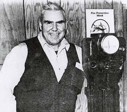
with the last operating electric staff system in North America.
"It's going to be retired", says Stewart Law, CP Rail's signal supervisor here. "We've all but run out of parts to repair it... The next time it breaks down, that's it".
As one of the first signal systems ever to be installed, it will probably end up in a railway museum along with other obsolete machinery and old photos.
It's a rather sad fate for the noisy antique. It still works fine, but Jim Styles, a 33-year CP Rail employee who is now an operator at Clarabelle Station, points out a major problem, the machine has been obsolete since it was purchased in 1912. This was discovered in 1930 when previous operators sent for new parts from the Liverpool manufacturer.
Despite this drawback, Mr. Law says it is most likely still being used in parts of Africa since it is a reliable forerunner of modern rail "traffic lights".
The electric staff system at Clarabelle controls a single section of track which is shared by the two national railways. A primitive form of traffic light, it informs engineers whether it is safe to proceed along the track or whether a train is already occupying the stretch.
INNER WORKINGS
The system consists of two parts. One machine, which resembles a small grandfather clock, is housed inside the station along with a generator. The other is located at the head of the junction. They operate through a series of brass and iron weights called "staves". When a train reaches the head of the junction and wishes to proceed to the station, a button is pushed at that end of the system. The button activates a bell in the station. This lets the operator know that a train is waiting to come into the junction. If a train is not already occupying the stretch, the operator will crank a generator to provide power to the electric staff system at the junction. The power loosens the machine's "grip" and a trainman is able to remove one of the staves.
Once a staff (the singular form of stave) is removed, the machine's dial will indicate that the rail line is blocked. If another train approaches the line, the engineer knows it is unsafe by reading the dial on the machine.
Once the staff is removed, it is placed in a leather pouch and kept on board the train until it leaves the junction. At that time, the staff is replaced in the machine and the dial turns to "staff in - (line) clear". The staves can also be removed or replaced at the station, since the machines are interconnectable.
Mr. Law expects that when the device is finally retired, engineers will receive radio permission to enter the junction. Other systems have been replaced by lights.
It will be a melancholy day when the staff system is banished to a museum. "A lot of people are going to miss it", Mr. Law admits. "We've been pretty proud of the old thing. It's not very often the younger generation get to work on something that still works the way it's supposed to... and it's still shiny as can be inside".
So long, oldtimer.
Westinghouse Brake and Signal Company Ltd.