
Canadian Pacific Staff Bulletin - February, 1947
On Two Company Locomotives
Result: Better Performance
The pioneer engines, operating between Montreal, Toronto, Winnipeg, and Regina, are part of the Company's program for the adaptation of the latest devices in the field of transportation.
It is hoped that the new fusion welded boilers will eliminate or reduce considerably some of the undesirable features of the usual rivetted type locomotive boilers, with a nine-point program of possible improvements set up, and the operating performance of the engines being carefully followed to see what results may bring.
The nine points of possible improvement being closely checked and what it is hoped they will do are:
- Eliminate cracks due to intergranular corrosion and high stress concentration in rivet
holes;
- Increase joint efficiency as compared to rivetting;
- Reduce weight by the elimination of lap joints, inside and outside welts, and rivets;
- Eliminate the possibilities of age-hardening of cold worked plates by final thermal stress-relief
heat-treatment;
- Eliminate high stresses around rivet holes due to rivetting operations;
- Eliminate stress risers due to abrupt change in section, such as the excess thickness at girth and
longitudinal seams of the rivetted boiler;
- With the more uniform contour of the interior and exterior of the welded boiler, permit ease of
application of brackets and facilitate cleaning the interior, due to the absence of welts and rivet
heads;
- Eliminate damage due to caulking of rivets and joints in the rivetted construction;
- Result in a more economical method of fabricating.
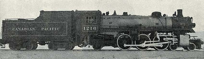
Work carried out by the mechanical engineering department of the CPR resulted in the fitting by the Montreal Locomotive Company of two new "1200" class engines (4-6-2 wheel arrangement) with the new boilers, built by the American Locomotive Company of Schenectady, New York. They are the first locomotives of this type to operate on Canadian lines, and are being run in regular service under varying operating conditions.
Decision to try them was prompted by the good service obtained from fusion welding in other instances, including a welded locomotive boiler now in service on the Delaware & Hudson. Permission of the Board of Transport Commissioners of Canada was necessary for installation of the boilers.
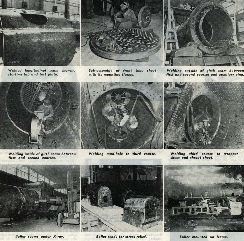
The boilers were built to operate at a working pressure of 250 pounds per square inch (psi) with a safety factor of five and an allowable joint efficiency of 90 percent. They differ from the Delaware & Hudson Railroad Company's boiler in that the barrel portion consists of three barrel courses butt-welded together and that a man-hole opening is provided in the third course to facilitate internal inspection in place of the conventional steam dome. The foundation rings are cast steel with single rivet construction, with the caulking edges of the inside and outside firebox sheets seal welded.
The smoke box is fastened to the first course by rivetting to facilitate renewing the smoke box which is renewed three to four times during the life of a locomotive boiler.
The wrapper sheet consists of a three plate construction which permits using a heavier sheet over the crown, thus eliminating the need for a liner, which is generally used to stiffen the crown of one-piece wrapper sheets.
The man-hole is flanged from 1 inch plate and has a 17 inch diameter opening, with an overall diameter of 34 1/2 inches fitted into the third course and attached with double-welded butt-weld. The boiler shell opening at the man-hole is reinforced with a liner 1 1/8 inch thick 25 inch I.D. by 40 inch O.D. which is attached to the man-hole flange and boiler shell by fillet welds at the inside and outside edges of the liner.
Pads for top check, washout opening, bracket attachments for dry pipes, and other internal and external fittings are fillet welded to the boiler shells prior to the stress relieving heat treatment.
All washout plug bushings and flexible staybolt sleeves were seal welded to the back head, wrapper sheet, and throat sheet after the boiler has been stress relieved.
The firebox door opening is formed in the usual manner, by flanging the outside back head inward and the inside back head outward. The two edges are joined together by a single welded butt-weld.
The front tube sheet is of the same design as that used in the Delaware & Hudson all welded boiler. It consists of a circular ring 1 1/4 inch thick by 4 3/8 inch wide, with a recess at the water side in which the tube sheet is fitted and fillet welded both sides. The complete tube sheet assembly is then fitted and fillet welded to the first course. The ring is provided with slots at the top and bottom centres in order that the tube sheet can be renewed without cutting any of the welds except those directly attaching the tube sheet to the circular ring.
Plates used in the boiler shells were carbon steel to A.S.T.M. specification A-201, Grade A, killed for
automatic submerged melt welding. The inside firebox sheets were carbon steel firebox quality to the railway
company's specification number 5.
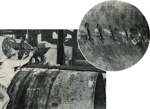
The girth and longitudinal seams of the barrel courses were prepared for automatic submerged melt welding on a plate planer, prior to rolling and forming. The inside and outside back head, throat sheet, back tube sheet, and fire door hole were prepared for manual welding by chipping and grinding. A tolerance of .015 was permitted in the gap between the plate edges which were automatic submerged melt welded and a 1/8 inch gap between joints that were welded manually.
To obtain the tolerance required for automatic welding it was found necessary to grind the butting faces prior to pulling them together. Large nuts were tack-welded to each side of the seams inside the boiler through which draw bolts were applied to hold the seams in line and for pulling the butting edges together. After each seam was properly lined up the plates were tack welded on the inside to maintain a good fit during welding on the outside. Clean-up grinding of the plate edges was also done in order to remove all dirt and scale which might have otherwise caused defects in the weld metal.
After the outside welds were completed, the draw bolts, nuts, and tack welds were removed and the inside of the seam made ready for welding.
All welding was in accordance with the A.S.M.E. Locomotive Boiler Code. Procedure qualification and operator's qualification tests were made to determine the suitability of the welding technique employed, welding apparatus, electrodes, plate material, and welding operator's ability to produce sound welds, under conditions similar to those used during erection of the boilers.
The procedure qualification tests consisted of the welding joints similar to those required for erection of the boilers, using the welding and rotating equipment employed during construction. A record of all qualification tests was kept for future reference.
The automatic submerged melt welding process was used to weld all longitudinal and girth seams where practical. Test plates were attached to the longitudinal seams of each barrel course and welded continuously with the seam.
Identification marks were attached to each test plate so that they could be identified in relation to the course from which they were taken. Test plates were stress relieved with the boilers and then given the physical test required. Physical test applied to the test coupons showed the joint to be superior to the parent metal in all cases.
All fillet welds and a small percentage of the irregular butt welds were made with the manual arc using A.W.S. E-6011 electrodes.
X-Ray was carried out in accordance with the A.S.M.E. Locomotive boiler code requirements.
For ease of locating possible defects, lead numbers were attached to a cloth strip at 2 inch intervals. The cloth was then attached to the boiler, close enough to the weld so that the lead numbers would show up on a 4 1/2 x 17 inch X-ray negative. The numbers started at the front of each longitudinal seam and at the front longitudinal seam running counter-clockwise when X-raying the girth seams. Light centre punch marks were also made alongside each seam at 10 inch intervals, to which lead arrows pointed, serving as a permanent means of locating defects.
When for example a defect was found on an X-ray negative, the negative itself was placed on the boiler and positioned exactly by placing the centre punch marks on the negative over those on the boiler, thereby eliminating any possible mistakes in locating defects.
The American Locomotive Company installed in 1945 at its Schenectady plant, a wagon-bottom indirect heating stress-relieving furnace, which is fully automatic on its heating, soaking, and cooling cycles.
Before placing a boiler in the stress relieving furnace, the foundation ring was bolted in place and the back head, wrapper sheet, throat sheet, and boiler shell were thoroughly braced to prevent distortion. After the boiler was mounted on the furnace base, thermal couples were attached at various locations of the boiler for control of heat input to the light and heavy sections during the stress-relieving operation.
The stress-relieving temperature was raised 100 degrees per hour until a maximum temperature of 1175 degrees was reached, the furnace was held at this temperature for two and one-half hours and cooled 100 degress per hour until a furnace temperature of 200 degrees was reached before the boiler was removed from the furnace.
The stress-relieving heat treatment was accomplished without any change in contour.
After the stress-relieving heat treatment, the firebox, staybolts, flexible staybolts, tube, flues, stay rods, and other internal fittings were applied.
The boilers were hydrostatically tested to one and one-half times the maximum allowable working pressure, and while under this pressure all unstayed seams were hammer tested by striking each side of the seams at 6 inch intervals. The boilers were then given the usual final steam test for locomotive boilers.
This Staff Bulletin article is copyright 1947 by Canadian Pacific Railway Limited
 and is reprinted here with their permission. All photographs,
logos, and trademarks are the property of the Canadian Pacific Railway Company.
and is reprinted here with their permission. All photographs,
logos, and trademarks are the property of the Canadian Pacific Railway Company.