
Railroad Car Lighting - Past and Present
It is difficult to keep fixtures clean on cars in which cinders and dust are prevalent, and dirty
fixtures discourage improvement in lighting. Several means have been used, such as louvers, particularly in
continuous-type trough fixtures, and plastic shades. Indirect lighting has also been used. Indirect lighting
alone, however, is not very efficient for car lighting when compared with direct lighting from well-designed
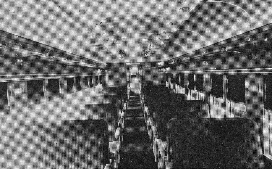
fixtures. It is agreed that the best location for lighting fixtures in coaches is under the baggage racks
providing suitable supplementary lighting is supplied to give adequate ceiling illumination. This location
brings the lights close to the reading plane and also permits individual control by the passengers. This
arrangement, however, is seldom feasible except on new cars, because of the cost of installation.
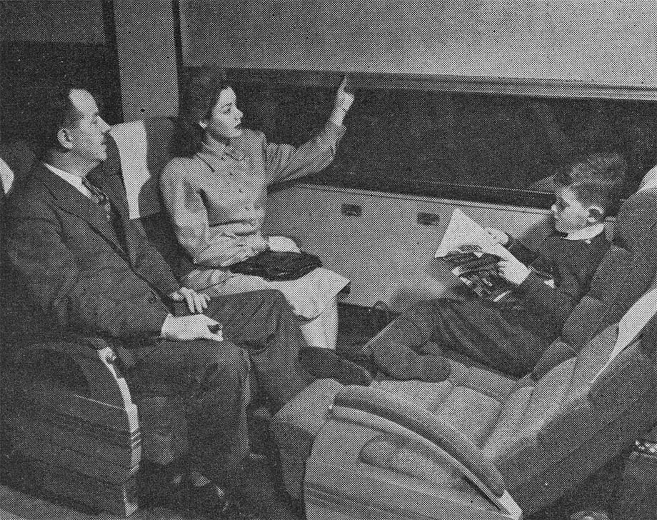
With air conditioning and modern lighting, reclining seats also were introduced on a large scale. With these came a demand for reduced lighting for use late at night, to permit passengers to sleep without being disturbed by the bright lights. A number of arrangements have been used for this purpose, such as dimming some of the main lighting units with the others extinguished, small additional fixtures being installed especially for the purpose, and the use of an auxiliary low-wattage lamp in the main fixtures, usually blue in color.
For night lighting, the body lights are extinguished, and the blue lights alone used for illumination in the body of the car. Platform, salon, and passageway lights are left unchanged, but shields are provided where necessary to prevent direct glare. Improvement of the body lighting led to an increase in the lighting in washrooms and salons, while the use of air-conditioning led to improved ventilation by installation of exhaust fans.
Not only has the total regulated load increased, but also the loss in the lamp regulator, which in turn,
requires improved ventilation of the regulator lockers. Even with the large-sized batteries used on
air-conditioned cars, the effect of these high-lighting loads becomes noticeable. In short, the increased
lighting load required by modern lighting indicates the desirability of a source of light more efficient than
the incandescent lamp, the only type so far considered.
Fluorescent Lighting
Fluorescent lamps were first placed on the market about 1938 and have had widespread acceptance for many uses since that time. The possibilities for power saving are immediately apparent. For instance, an 18 inch by 1 1/2 inch (T-12) 3,500 degree white fluorescent lamp with 15 watts input to the lamp and about 5 watts loss in the auxiliary or a total input from the line of 20 watts gives about four percent more light than a 40 watt incandescent lamp. Exclusive of conversion losses, the power required can be cut in half for approximately the same light.
The advantage of this type of lighting is the more even distribution of light obtained than with the incandescent lamp, due to the larger source of illumination. Also, the effect of voltage variations on light output is less than with the incandescent lamps, a one percent voltage change making a 1 to 2 1/2 percent change in the light from a fluorescent lamp, whereas it makes a 3 1/2 percent change in the light from an incandescent lamp.
Fluorescent lamps, however, have some disadvantages, such as the lamps not lighting or staying lighted below a certain voltage, also lamps operated on AC circuits are sensitive to frequency variations, 58 to 62 cycles being accepted as the standard range. Fluorescent lamps were designed for operation from an AC supply only when first brought out. Therefore, for car lighting, some device was required to convert from direct to alternating current, And most of our problems have been associated with conversion devices.
At present, two methods of changing direct to alternating current are used, vibrators or motor alternators. There is one type of vibrator inverter installation known as the "constant load" type, in which no provision is made for turning off individual lamps. These inverters have a relatively high efficiency of approximately 70 percent.
A useful piece of equipment is a motor alternator, which is merely a small motor-generator set having a single-phase generator. The set is provided with inherent regulation of voltage and speed, and standard commercial auxiliaries are used with the lamps. Because of the simplicity and ruggedness of these machines, quite a number are in use, although efficiency is less than that of the vibrator inverter, the efficiency being 60 percent at full load and less at light loads.
It may be noted that both the above systems eliminate the lamp regulator, which helps to improve the efficiency. The efficiency can drop to approximately 38 percent before the input of a fluorescent lamp installation will equal that of an incandescent lamp installation for the same amount of light.
Fluorescent lamps will also operate successfully on direct current. However, the range in voltage over which such lamps will operate is somewhat limited. With the voltage on the so-called 64 volt system actually varying from 56 to 90 volts when using Edison batteries, it was found necessary to develop a new size lamp to secure one that would start and operate on voltages down to 55 volts, which is considered as the lower limit of required operation.
Over the past twelve or fourteen years, a large number of passenger cars have been equipped for fluorescent lighting, including operation of conventional types of fluorescent lamps in series, using cold cathode starting, and also with the use of neon tubes. One railroad which has ordered over 400 cars since the end of the last war has used 60 volt DC fluorescent lighting, but the majority of other railroads have used the 60 cycle, AC fluorescent lighting.
Post-War Improvements
As coaches constitute a large part of passenger-carrying rolling stock, they are being discussed, for the most part in this article. The levels of illumination provided in passenger cars previous to 1936 were, in general, considerably below that of dining and other special types of cars. Furthermore, the lighting of cars other than coaches often influenced to a much greater extent by the desire to apply architectural and decorative treatment to the lighting.
Heavy Drag on Locomotives
In the Eastern United States, most of the new cars are being equipped with axle-driven generators. In the West, where the railroads have to contend with long grades, which require full locomotive power output for traction purposes, many have adopted engine-driven generators for lighting, and engine-driven compressors for air-conditioning. Most of these units use propane fuel.
The larger generators on many of these cars are driven by a gear unit, consisting of a hypoid gear mounted on a quill which rotates on anti-friction bearings. The gear drives a hypoid pinion which is also mounted on anti-friction type bearings. When a motor-generator set is used, an automatic clutch is provided in place of a simple safety clutch. This clutch engages and releases automatically. It engages when the drive shaft from the axle of the car is rotating at approximately 280 r.p.m. This type of clutch permits the motoring of the generator by means of the AC motor mounted on the same shaft.
Most railroads require that any passenger car be capable of carrying its air-conditioning load for at least two hours, independent of any outside power source, which requires a relatively large battery. These batteries must be charged at a relatively high rate, while the car is running, putting a heavy drag on the locomotive. For example, a 15 car train may require as much as 600 h.p. from the locomotive for the electrical power taken by the cars. This is an appreciable percentage of the locomotive rating for normal operation.
On some railroads, the variation in the number of cars that have to be hauled by the same locomotive in different trains may be so great, that no credit can be given to a self-contained power plant for the saving of locomtive horsepower.
On the other hand, where trains of the same length are hauled by the same locomotive day after day, the saving in locomotive horsepower can be credited to the self-contained power plant. The trend, however, appears to be toward the use of single engine-driven units for the supply of electro-mechanical air-conditioning, fluorescent lighting, and all other power services on the car.
Having long realized the advantages of induction motors for use on passenger cars, instead of commutator
motors, the advantage of AC power has been forcefully brought to the attention of the railroads by other
innovations, such as fluorescent lighting, electric razors, radios, public address systems, sound movies,
etc.
Diesel-Driven Power Plants
Since diesel fuel has become available on most railroads, attention has turned to diesel-engine-driven power plants that can be mounted under the car. Several manufacturers are developing or have produced units for undercar mounting. Advances made during the last war in the design and building of reliable small engines, and also advances made in design and construction of AC generators and the voltage-control components, have made this possible.
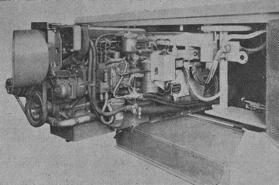
The following description covers one type of undercar diesel-driven power plant, produced by the General Electric Company and used on their "More Power to America" train.
The power plant mounts under the passenger cars to supply power for lighting, air-conditioning, electric heat and other electrical loads. By special addition, recovery of exhaust-gas heat and jacket-water heat can be installed to augment the electric heating units. These power plants will operate in parallel with other duplicate power plants in the train. The alternators are designed so sets may be paralleled automatically without pre-synchronization.
The box which carries this unit has a sound-insulation lining, and is fitted with shock mounts at the points of support to the car to reduce noise and vibration. Included in this box is a steam coil, which is connected to the steam tramline and is used during standby in cold weather to keep the power plant warm and facilitate starting.
The engine is a Buda-Lanova 6 cylinder, 4 cycle, 48 h.p., 1,800 r.p.m. machine, with engine governor having 6 percent regulation to permit bus line operation. The alternator is direct-connected to the diesel engine and is a 4 pole rotating armature machine with a net output of between 27 and 30 kilowatts while overhung from the alternator is an amplidyne exciter, used solely for supplying alternator excitation. It is controlled by a static-type voltage regulator.
This entire power plant is controlled from a simple three-position control station. Engine cranking is automatic, being stopped when the engine starts or at the end of thirty seconds. A 200-ampere-hour, 32 volt battery is used to provide DC power for engine cranking, control circuits, and a limited amount of emergency lighting.
A rectifier-type battery charger provides continuous charging from the 230 volt, 3 phase load bus while the plant is in operation. The engine-cranking time delay relay is a magnetic-pneumatic-type relay providing 30 second time delay on pickup. Its normally closed contacts de-energize the cranking contactor if the engine fails to start in 30 seconds.
With the exception of dining cars equipped for full scale electric cooking, and cars equipped with nurseries and entertainment, the author has traced the development of car lighting as carried out by the Canadian Pacific Railway with which he is connected.
Other railroads have progressed along similar lines but to describe all the types of installations that have been made would require a book, not an article. Practically all the new installations have been fully described in either the Railway Age or the Railway Mechanical and Electrical Engineer.
 Railway Limited and is reprinted here with their permission. All photographs, logos, and
trademarks are the property of the Canadian Pacific Railway Company.
Railway Limited and is reprinted here with their permission. All photographs, logos, and
trademarks are the property of the Canadian Pacific Railway Company.
