
1 April 2008
Inspecting Four Prominent Bridges
(Abridged - no pun
intended)
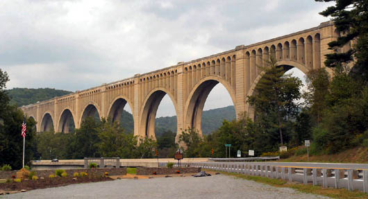
Tunkhannock Viaduct in Nicholson, Pennsylvania, owned by
Canadian Pacific Railway.
Nicholson and Kingsley Pennsylvania USA - The period from
the mid-1890s through World War I was a "golden age" of railroad bridge engineering in North America. Hardesty
& Hanover, LLP, had the privilege between mid-2005 and mid-2006 to inspect four prominent railroad
structures that date to the first 20 years of the 20th Century.
The bridges are:
- Little Hell Gate Bridge in New York, N.Y., owned by Amtrak;
- Tunkhannock Viaduct in Nicholson, Pa., owned by Canadian Pacific Railway;
- Martin's Creek Viaduct near Kingsley, Pa., owned by Canadian Pacific Railway;
- Connecticut River Bridge in Old Saybrook, Conn., owned by Amtrak.
In addition to inspection, three out of four of the structures were completely analyzed for load-rating capacity (seismic
excluded). Specialized ultrasonic pin testing and concrete testing were performed.
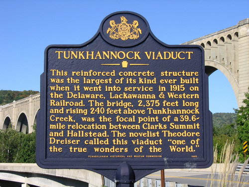
Tunkhannock Viaduct historic
marker.
Tunkhannock and Martin's Creek Viaducts
The Tunkhannock Viaduct is a 12-span reinforced concrete arch bridge that, at the time of its completion in 1915, was the
largest concrete bridge in the world. The structure was designed by Abraham Burton Cohen and constructed by the Delaware, Lackawanna
and Western Railroad as part of the Hallstead Cutoff.
Tunkhannock (also known as the Nicholson Viaduct) was constructed to eliminate the difficult grade changes that the railroad
encountered along its original path on what is now Pennsylvania Route 11. The construction of the bridge also shortened the travel
distance of trains between New Milford and Clarks Summit by 3.5 miles. It was originally designed to carry two tracks, but today
carries only one along its eastern side that services both northbound and southbound freight trains from Binghamton, N.Y., to Scranton,
Pa. The bridge stretches 2,375 feet across the rural valley over which it is sited, and soars 240 feet above the east branch of
Tunkhannock Creek at its highest point. The Tunkhannock Viaduct is a designated historic civil engineering landmark of the American
Society of Civil Engineers.
The structure has 10 visible spans, each measuring 180 feet in length, and is flanked by two abutment spans that were buried during
construction. Each of the piers is founded on bedrock, which at the time of construction was up to 138 feet below grade. Nearly half of
the structure's mass is buried underground.
There are reportedly an average of 10 freight trains per day carried on the line at present. The closed western track line area now
serves as an access road along the full length of the bridge. The track is supported on timber ties that rest in a ballast and gravel
bed. The ballast is supported by a reinforced concrete bridge deck, which was constructed with an applied waterproofing system.
Three-foot-thick reinforced concrete parapets extend the length of the bridge along each fascia.
At the visible spans, the concrete deck was poured atop reinforced concrete spandrel arches, which are then supported by reinforced
concrete spandrel walls. In each span, there are 12 spandrel walls, 10 of which are supported on the arch ribs themselves. The two end
walls comprise a portion of the tower at each support pier. The spandrel walls apportion the span into 11 equal-length
panels. The main structural elements of each span are the east and west reinforced concrete arch ribs (the spandrel walls separate in
an archway at varied elevations above the ribs) that spring from each pier 125 feet below the top of deck.
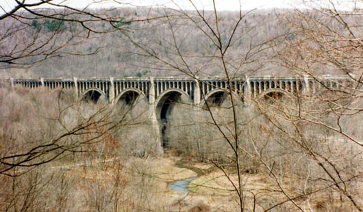
Martin's Creek Viaduct near Kingsley, Pennsylvania, owned by
Canadian Pacific Railway.
The Martin's Creek Viaduct is a 10-span reinforced concrete arch bridge, built in conjunction with the Tunkhannock
Viaduct (nine miles distant) as part of the Hallstead Cutoff project. The Martin's Creek Viaduct is 1,600 feet long with
150-foot-high arches. The structure was completed in 1914 and was originally constructed with three tracks. Today it
carries a single center track, which services both northbound and southbound trains on the rail line.
The geometric makeup of the bridge varies for the first three spans. Spans 1 and 2 are short single-arch spans that
directly support the railway deck. Spans 3 through 10 are similar to the visible spans of the Tunkhannock Viaduct. Each span consists
of two arch ribs that support a series of spandrel walls, which in turn support the spandrel arches and deck above. Reinforced concrete
parapets extend the length of the bridge along each fascia. Span 3 is shorter than Spans 4 through 10. The span supports seven spandrel
walls, five of which rest directly on the arch ribs. Spans 4 through 10 each support eleven spandrel walls, nine of which rest directly
on the arch ribs. The two end walls comprise a portion of the tower at each support pier. The ten piers supporting the structure are
buried deep below grade. The north abutment span similarly consists of two reinforced concrete arch ribs supporting four spandrel
walls, which, in turn, support the deck above. Concrete sidewalls block in the span along the east and west fasciae. A significant
portion of the north abutment span is buried under fill material.
Concrete Testing
Limited concrete investigations were performed for the viaducts, the overall purpose being to sample the concrete to check compressive
strength against rating analysis assumptions, and to verify some of the mechanisms causing deterioration for estimating the repair
quantities and costs. After initial examination of core samples indicated evidences of Alkali-Silica Reactivity,
petrographic analysis was performed on two of the core samples to check the extent and the activity of the ASR. It was found that the
concrete, while having suffered the effects of freeze-thaw and ASR, was generally in a stable state. It was recommended
that a rehabilitation that addresses the visually observed areas of surface deterioration would likely suffice to repair the structure
for continuous, acceptable service.
Among the unique access issue, at Martin's Creek Viaduct, during inspection the field crew found that the railroad
right-of-way access road to the site had been severely rutted during the winter and early spring due to recent, heavy
rains, such that the inspection equipment could not gain access to the bridge. The remote and mountainous terrain prohibited alternate
access means. CP Railway crews were not available to respond to the situation, because of emergent conditions on other railway bridges
within the territory, also caused by the recent heavy rains and severe flooding in the Susquehanna River Valley. This situation
threatened costly delays to the project.
The H&H inspection team leader at the site was experienced with operation of small construction equipment. Without delay, the
inspector rented a small bulldozer for the day, performed the necessary grading work of the access road. All work was outside the
limits of the FRA fouling envelope for the active tracks. After the minor but necessary roadway repair work was done, the inspection
team accessed the site, and the inspection team leader informed the home office of the completed work.
The viaducts have a height of up to 240 feet above the valley floor. The inspection plan required coordinating a variety of access
equipment to effectively access portions of the structure for hands-on inspection.
As a safety measure, the local fire and rescue departments were notified prior to the inspection of the work being performed, so that
they might be prepared in the unlikely event of the need for emergency rescue.
To access the lowest portions of the structures, a 135-foot man-lift was used where ground access permitted.
To access the upper portions of the structure, an Underbridge Inspection Unit (UBIU) with a 60-foot reach was used.
Rail-mounted units are available. However, where an access road is available, using road-based vehicles is
vastly preferable, to avoid scheduling, and other access issues with track time. Track time availability was very limited for our use
at Tunkhannock and Martin's Creek Viaducts.
To access the mid-height portions of the structure, a spider basket attached to a truck-mounted crane was
used. Safe climbing using harnesses was also employed, along the top and center of the arches where the edge falling hazard was more
than one body-length distant.
The detailed, site-specific work inspection plan was particularly important for efficiently coordinating the use of crews
and equipment at these two structures. The comprehensive inspection of these massive concrete structures was accomplished in just a few
weeks time. Due to the difficulty in accessing some areas from the top of deck or from ground level (a result of structure size, site
topography, and obstructions), it was determined to be economically unfeasible to inspect every surface of the structure
hands-on. The best use of inspection resources within the allotted schedule was to perform a complete and thorough visual
inspection of the structures using reasonable access methods, and then to focus on close-up inspection of a representative
span at each structure, and to extrapolate these inspection data to other spans. By following this methodology, the inspection teams
focused more on the behavior of the structure and on overall rehabilitation needs. The similarities in deterioration conditions and
locations throughout the structure were noted.
The Tunkhannock and Martin's Creek Viaducts are composed of Portland Cement concrete, with steel reinforcement. However, the design for
the structures is not based upon modern reinforced concrete principles, but rather on unreinforced masonry design practices of the 19th
Century using mass concrete in place of stone masonry. Additionally, loading conditions used for the original design differ from
current AREMA recommendations.
For live loads and impact loads for Tunkhannock Viaduct, the 1911 stress sheets show a non-Cooper series of locomotive
wheel concentrations.
The wheel concentrations were positioned on the spans to produce the maximum stresses in the arch rib for two live load cases, namely
1) live load plus impact applied to the full span length, and 2) live load plus impact applied to one-half the span length.
The original stress sheets apply the live load to the arch rib as concentrated loads at the spandrel columns. Since the concentrated
loads are proportional to the spacing of the spandrel columns rather than the magnitude and location of the wheel concentrations, it is
apparent that an equivalent uniform live load was used as part of the original design. It appears that the original stress sheets
calculated the concentrated loads at the spandrel columns as follows:
Locomotive axle loads were positioned on the span for maximum stress at the arch rib. Once positioned, the concentrated loads were
summed and divided by the loaded length to generate a uniform load. A distribution factor was applied to the live load. The live loads
were then divided by the width of the arch rib to generate an equivalent uniform load per unit width of arch rib. The concentrated
loads at the spandrel columns were then determined by calculating the reactions of the equivalent uniform live load, considering the
tributary area to be one half of adjacent concrete deck span lengths.
From review of the concentrated live loads tabulated in the stress sheets and working backwards using this procedure, uniform track
loads were derived.
Temperature loads are calculated on the 1911 stress sheets based on a temperature rise of 30 degrees F and a temperature fall of 30
degrees F.
1911 Load Combinations were:
- Dead Load + Temperature;
- Live Load + Impact on half the arch span + Dead Load + Temperature;
- Live Load + Impact on full arch span + Dead Load + Temperature.
No other loads or combinations were used in the original design.
The main arch ribs of the Tunkhannock Viaduct were constructed by the alternate block or "voussoir" method. With this method,
the arch rib is constructed in transverse blocks of such size that each block can be completed at one pouring, or within about a day's
work. The blocks are poured in such an order as to give a uniform deflection of the centering, and also prevent the crown of the arch
from rising as the lower arch loads are placed. This method has the advantage of reducing shrinkage stresses in the arch ring to a
minimum.
Steel centering was employed in the construction of the Tunkhannock viaduct. From 1918 Concrete Engineers Handbook by Hool and Johnson,
the use of three hinged steel centering had the following advantages:
- Crown deflection using steel centers is usually much less than that obtained by employing timber falsework;
- It is possible to compute the deflection of each point of a steel center with some degree of accuracy while, in the case of a
wooden center, the probable settlement at each bent is much less definitive;
- The advantage of allowing the deflection to be quite accurately computed makes it possible to give the centers a preliminary
camber so that when the concrete is in place and the centering withdrawn, the arch ring will assume its true position;
- The unique feature in the steel centering used in constructing the Tunkhannock Viaduct was an adjustable panel at the crown of
the steel arch trusses.
The above information on construction method is important to the proposed load rating analysis methods for the following reasons:
- The alternate block method of construction tells us concrete shrinkage stresses during construction were kept to a minimum;
- The arch ribs are not monolithic, but are composed of a series of concrete blocks, with a series of construction joints along the
entire rib length. It is assumed that if a particular section of the rib is subjected to high bending moments, these construction
joints will crack, effectively forming a hinge to redistribute the forces;
- Since steel centering trusses were used, it is assumed that deflection of the centering was accounted for during construction and
arches were constructed in their "true" position.
Analyzing the structures using finite element computer programs provided many opportunities for deep thought, review of assumptions,
re-analysis, and further, iterative computational processes, until rational analysis results were obtained.
Some of the modeling assumptions that were found to have significant effects on distribution of loadings and structural stresses
included the following:
- How is the arch spring restrained? Is the main arch best modeled as a two-pin, three-pin or fixed
structure? The answer to these questions required research into the original construction method employed for the arch, as
explained above, and as further explained below;
- Do the spandrel walls sit atop the arch simply as dead load? For Tunkhannock Viaduct's dead loads, the 1911 stress sheets apply
the design dead load from the ballasted deck and spandrel walls to the arch ribs as concentrated loads at the base of the spandrel
walls. The self weight of the arch rib is applied as a series of concentrated loads along the length of the arch rib. If the
spandrel walls interact with the arch, is their connection pinned or fixed? The arch ribs were modeled as a series of continuous
segments or members with fixed end supports at the skewbacks. During the initial analysis of the 180-foot spans, the
"dead load plus temperature fall" load combination generated relatively-high moments at the arch crown.
What concrete strength should be assumed? This was a particularly interesting problem. Concrete modulus of elasticity was shown as two
million pounds per square inch on 1911 stress sheets. From 1918 Concrete Engineers Handbook, a modulus of elasticity for concrete equal
to 1/15 that of steel may be assumed when the strength of the concrete is taken as greater than 800 psi and less than 2,200 psi.
Based on the above information, the load rating analysis assumed a design concrete strength fc'= 2,000 psi. Concrete core samples,
however, all tested well in excess of 3,000 psi capacity. Still, the original design assumptions regarding elastic modulus were found
to be most appropriate for obtaining rational and balanced results.
Load ratings were computed in accordance with AREMA (2006) Chapter 8, Concrete Structures and Foundations, Section 19, Rating of
Existing Concrete Structures. A two-dimensional linear element analysis was performed using SAP 2000 Integrated Software
for Structural Analysis and Design. Similar to the 1911 stress sheets, the arches were analyzed as independent spans. For the load
rating evaluation of the arch rib and spandrel walls, ultimate strength axial force versus bending moment interaction diagrams were
constructed and the main arch ribs and spandrel walls were rated by the load factor method. The deck sections were analyzed
independently by hand calculation using the working stress method.
Acknowledgements
We express our thanks to the following individuals and organizations for efforts related to the subjects of this paper:
David Gerber, P.E., Associate Engineer, Hardesty & Hanover, for rating analysis of Tunkhannock and Martin's Creek Viaducts.
David Killingbeck, P.E., Manager Structures Inspection at Amtrak (Project Manager for Little Hell Gate Bridge inspection project).
Kenneth Kulick, P.E., Director Structures Design at Amtrak (Project Manager for Connecticut River Bridge inspection project).
James Richter, P.E., Deputy Chief Engineer Structures at Amtrak (review of draft paper).
John Unsworth, P.E., Manager Structures Planning & Design at Canadian Pacific Railway (Tunkhannock and Martin's Creek Viaducts,
Project Manager for inspection project).
John Wood, P. E., Senior Structural Engineer, Structures Planning and Design, CP Railway for review of load ratings of the viaducts.
References
1. Ammann, Othmar, ASCE Transactions Vol. LXXII, Paper No. 1417 presented 21 Nov 1917.
|